7.3 AASHTO Overlay Thickness Design for Unbonded Concrete Overlays
The 1993 AASHTO Guide for Design of Pavement Structures is recommended for unbonded concrete overlay thickness design. The designer can use the AASHTO DARWin® 3.1 program and select the “Overlay Design” Module and “Unbonded PCC Overlay of PCC Pavement.”
7.3.1 Overlay Thickness Design
D
ol
= (Df
2
- Deff
2
)1/2
Where:
D
ol
- required slab thickness of overlay, in.D
f
= slab thickness to carry future traffic, in.D
eff
= effective thickness of existing slab, in.Determination of Effective Slab Thickness by Condition Survey Method
D
eff
= Fjcu
* DWhere:
D = existing slab thickness, in. (Use 10 in. when existing D > 10 in.)
F
jcu
= joints and cracks adjustment factorF
jcu
adjusts for PSI loss due to unrepaired joints, cracks, and existing expansion joints, exceptionally wide joints (> 1 in.), or AC full-depth patches.Use the total number of unrepaired deteriorated joints, cracks, punchouts, and other discontinuities per mile in the design lane to determine the F
jcu
from Figure 8-6.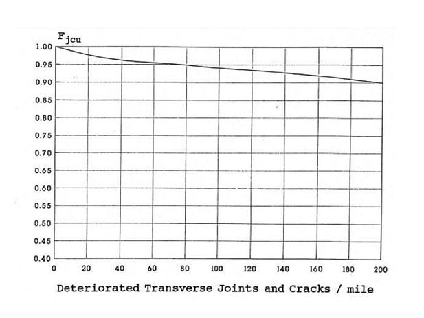
Figure 8-6. Joints and Cracks Adjustment Factor for Unbonded Overlays, Fjcu Source: AASHTO Guide for Design of Pavement Structures (1993)
7.3.2 Reinforcing Steel Design
The reinforcing steel placements are the same as new CRCP when unbonded overlay is 7 in. or thicker. When unbonded overlay is less than 7 in., use longitudinal reinforcement at about 0.6% of concrete cross-sectional area. The design engineer will determine the steel bar size and quantities for longitudinal bars, tie bars, and transverse bars, and consult with the Pavement Analysis & Design Branch of MNT – Pavement Asset Management.
More information about bonded and unbonded concrete overlays is detailed in “Bonded Concrete Overlay” and “Unbonded Concrete Overlay” in Chapter 10, “Rigid Pavement Rehabilitation.”