7.2 AASHTO Overlay Thickness Design for Bonded Overlays
The equation below is used to calculate the overlay thickness to increase structural capacity to carry future traffic. The designer can also use the DARWin® 3.1 program and select the “Overlay Design” Module and “Bonded PCC Overlay of PCC Pavement.”
D
ol
= Df
- Deff
Where:
D
ol
= required slab thickness of overlay, in.D
f
= slab thickness to carry future traffic, in.D
eff
= thickness of existing slab, in.The slab thickness, D
f
, is determined for the design traffic as if it were built as a new pavement on the prepared base. Use the design procedure in Sections 3 or 4 for the pertinent pavement type. Some existing pavements might not have stabilized bases, and the k-value should be evaluated using FWD or DCP.Determination of existing Effective Slab Thickness by Condition Survey Method
D
eff
= Fjc
* Fdur
* Ffat
* DWhere:
F
jc
= joints and cracks adjustment factorF
dur
= durability adjustment factorF
fat
= fatigue adjustment factorD = thickness of existing slab, in.
For BCO design, the condition of the existing pavement is one of the most important factors. If the pavement condition is deteriorated in the form of punchouts and deteriorated cracks, BCO may not be a good alternative.
The items that should be surveyed are:
- the number of punchouts per mile,
- the number of deteriorated transverse cracks/joints per mile,
- the number of existing and new repairs prior to the overlay per mile,
- presence of D-cracking or ASR cracking, and
- evidence of pumping of fines or water.
Punchouts are the only structural distresses in CRCP; the number of punchouts per mile is a good indication of the structural condition of the existing pavement. If there are more than 12 punchouts per mile, then the pavement is in poor structural condition and may not be a good candidate for BCO.
The number of deteriorated transverse cracks per mile is the next item to be surveyed. Even though some transverse cracks may appear to be deteriorated, quite often they are structurally in good condition. In Texas, it is rare to observe deteriorated transverse cracks, except for spalled cracks. Most spalled cracks are not necessarily structurally deficient. Based on the research findings, it is recommended that only transverse cracks much wider than normal, along the entire length of the transverse crack and across the entire lane width, should be counted as “deteriorated transverse cracks.”
The number of patches per mile and evidence of pumping should be recorded. In Texas’ old concrete pavements, typically, the base was not stabilized and pumping resulted. Durability related problems, such as D-cracking and ASR cracking, should be noted and their severity recorded. Overall, it has been quite rare to observe durability-related problems in concrete pavement in Texas.
7.2.1 Joints and Cracks Adjustment Factor, F
jc
The Joints and Cracks Adjustment Factor, F
jc
, accounts for the extra loss in the present serviceability index (PSI) caused by deteriorated reflection cracks in the overlay. Deteriorated reflection cracks develop due to unrepaired deteriorated joints, cracks, and other discontinuities in the existing slab prior to the overlay.A deteriorated joint or slab will rapidly reflect through an overlay and contribute to loss of serviceability. Therefore, full-depth repair is recommended on all deteriorated cracks and any other major discontinuities in the existing pavement prior to overlay. The target F
jc
is 1.00.If it is not possible to repair all the deteriorated areas, use the total number of unrepaired deteriorated joints, cracks, punchouts, and other discontinuities per mile in the design lane to determine the F
jc
from Figure 8-5.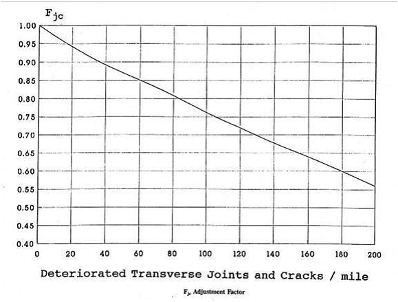
Figure 8-5. Joints and Cracks Adjustment Factor for Bonded Overlays, Fjc. Source: AASHTO Guide for Design of Pavement Structures (1993)
7.2.2 Durability Adjustment Factor, F
dur
The Durability Adjustment Factor, F
dur
, adjusts for an extra loss in PSI of the overlay when the existing slab has durability problems, such as D-cracking or reactive aggregate distress. Fdur
is determined using historical records and condition survey data. Table 8-5 shows the durability adjustment factor.Durability Adjustment Factor, F dur | Historical Records and Condition Survey Data |
|---|---|
1.00 | No evidence or history of PCC durability problems. |
0.96 – 0.99 | Pavement is known to have PCC durability problems, but there is no visible spalling. |
0.88 – 0.95 | Cracking and spalling exist (in these conditions, a bonded PCC overlay is not recommended). |
7.2.3 Fatigue Damage Adjustment Factor, F
fat
The Fatigue Damage Adjustment Factor, F
fat
, adjusts for past fatigue damage in the slab. It is determined by observing the extent of punchouts (CRCP) that may be caused primarily by repeated loading. Table 8-6 shows the fatigue damage adjustment factor.Fatigue Damage Adjustment Factor, F fat | Historical Records and Condition Survey Data |
|---|---|
0.97 – 1.00 | Few transverse cracks/punchouts exist (none caused by D-cracking or reactive aggregate distress), < 4 punchouts per mile. |
0.94 – 0.96 | A significant number of transverse cracks/punchouts exist (none caused by D-cracking or reactive aggregate distress), 4 to 12 punchouts per mile. |
0.90 – 0.93 | A large number of transverse cracks/punchouts exist (none caused by D-cracking or reactive aggregate distress), > 12 punchouts per mile. BCO is not recommended. |
7.2.4 Reinforcement Design
Reinforcement should be placed at a depth that provides a minimum concrete cover of 3 in. When BCO thickness is 3 in. or less, reinforcement in the form of longitudinal steel is not recommended. For thinner overlays, fibers have been successfully used.
The design engineer will determine the reinforcement bar size and number of longitudinal steel, tie bars, and transverse steel. The performance of CRCP depends on the percentage of longitudinal steel. Failing to place longitudinal steel in a BCO 4 in. or thicker will effectively reduce the percentage of longitudinal steel in the combined slab, which could increase steel stresses and make transverse crack widths larger. See the recommended reinforcing steel percentage and vertical location in Table 8-7.
BCO Thickness | Longitudinal Steel (%) | Vertical Location | Fibers |
|---|---|---|---|
≤ 3 in. | N/A | N/A | Yes |
≤ 5 in. | 0.6% | Bottom of BCO | No |
> 5 in. | 0.6% | Middle of BCO | No |