6.6 Texturing Operations
Surface texture is required to provide skid resistance and to prevent hydroplaning. Skid resistance is achieved from a combination of the fine aggregate and carpet drag. Hydroplaning is minimized by tining. A carpet drag texture and a metal-tine texture finish are required for all areas with a posted speed limit in excess of 45 mph. When shown on the plans, a carpet drag texture can be the only surface texture required for areas with a posted speed limit less than 45 mph.
When carpet drag is the only surface texture required by the plans, ensure that adequate and consistent coarse texture is achieved by applying sufficient weight to the carpet and keeping the carpet from getting plugged with grout. The target carpet drag texture is 0.04 in., as measured by Tex 436-A. Any location with a texture less than 0.03 in. must be corrected by diamond grinding or shot blasting. The engineer will determine the test locations at points located transversely to the direction of traffic in the outside wheel path.
Figure 9-59 shows an upside-down artificial carpet pulled longitudinally on the plastic concrete. This gives the concrete surface a rough texture similar to a broom finish.
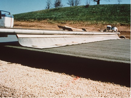
Figure 9-59. Artificial carpet drag.
The carpet shall be a single piece long enough to reach across the width of the plastic concrete and having enough longitudinal length in contact with the concrete to produce the desired texture. The engineer may allow changes in the length and width of the carpet to accommodate specific applications.
To keep the mortar from hardening on the carpet, the carpet should first be wetted before using and it should be cleaned with water often enough to produce a uniform finish on the concrete. Streaking of the surface behind the carpet is caused by hardened grout on the carpet. The contractor should stop the drag as soon as the streaking is observed and remove any dried grout from the carpet.
Figure 9-60 shows the mounting of a carpet. The carpet shall be mounted on a movable support system capable of varying the area of carpet in contact with the pavement and can be pulled either mechanically or manually.
To keep the carpet in contact with the concrete, the trailing end of the carpet may be weighted down with something that will provide enough weight to produce the desired texture.
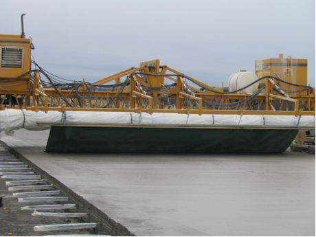
Figure 9-60. Mounting of artificial carpet.
Keep an eye on the drag ‑ it can indicate some things about the concrete. If it starts to catch and pull aggregates to the surface instead of leaving a uniform texture, there are two things that could be wrong:
- The concrete might not be properly vibrated. Check the vibrators to ensure that all concrete is being vibrated.
- There may not be enough sand in the mix to allow grout to be worked to the surface.
After the carpet drag operation is completed and the concrete surface has set enough, tining operations can begin. The default tining is transverse (see Figure 9-61); however, longitudinal tining is acceptable when shown on the plans. The metal tines should make grooves in the plastic concrete which are 3/16 in. deep and 1/12 in. wide. The minimum groove depth is 1/8 in. The grooves shall be spaced approximately1 in., center-to-center, for transverse tining, or 3/4 in., center-to-center, for longitudinal tining. If noise is a concern, longitudinal tining has been shown to be quieter than transverse tining.
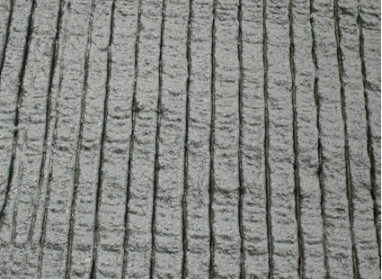
Figure 9-61. Transverse tined Surface.
To ensure that the grooves are straight, the tines should be pulled by a mechanized device. The mechanical device is designed to tine up to a 24-ft. wide concrete pour. Figure 9-62 shows a mechanical tining device.
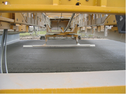
Figure 9-62. Mechanical tining device.