6.3 Slip-form Paving
Slip-form paving is the most widely used paving method in modern concrete paving construction. The slip-form paver consolidates, screeds, and initially finishes the concrete in one continuous operation without the need of forms. Modern slip-form paving equipment is of the extrusion-type process. The extrusion process can be simply defined as forcing, pressing, or pushing a material through a die or mold to create the desired shape. Slip-form paving is very efficient and can provide smooth concrete pavement. Because there are no forms, the plastic concrete must be able to hold the pavement edge. When slip-forming, the desired slump of the concrete is 1-1/2 in.
6.3.1 Alignment and Grade
The “stringline” is actually a slender wire rope. It is usually tensioned fairly high to reduce sags in the wire between the supports. A sensor on the paving machine will follow the stringline and any sags will show up in the final ride surface as waves that can produce an unpleasant ride quality.
A stringline is established to control the slip-form paving equipment at the proper grade and alignment. A surveying crew establishes a stake line every 25 or 50 ft. along, but offset from the edge of the pavement to be placed. Wood stakes used for this line are about 1-1/2 to 2 in. square, commonly called hubs, and are driven into the ground. The alignment is then established with a tack in the top of each stake. Grade is also established by elevation grading of each stake. For hard, dense subgrade such as an asphalt bond breaker, nails driven into the subgrade are used instead of wooden stakes with tacks. Using the line and grade from this survey line, a stringline is established for the slip-form paving machine to follow utilizing the machine’s electronic grade and alignment controls. Usually, another graded stake line is established along, but offset from, the other edge of the pavement to control the grade of that side of the paving machine; however, alignment is only controlled from one stringline.
6.3.2 Overview of Slip-form Paver
Slip-form paving is accomplished by the use of several self-propelled machines in a line which is commonly known as a paving train.
The first machine in line is a concrete placing machine and, depending on the manufacturer, this machine is sometimes referred to as a placer/spreader. This machine receives the mixed concrete from the delivery vehicles and places and spreads the concrete in front of the second machine, which is the slip-form paver. Sometimes this first machine is eliminated if the concrete can be deposited directly in front of the slip-form paver from the concrete delivery units or if a concrete placing attachment is installed in the front of the slip-form paver.
The slip-form paver spreads the concrete uniformly across the paving area with an auger, consolidates the concrete with spud vibrators, and strikes off the top of the concrete to a suitable elevation to feed into the mold that shapes the pavement into the proper geometric configuration. Depending on the manufacturer, some slip-form pavers also utilize what is known as a tamping bar. The tamping bar slightly tamps large aggregates into the top of the concrete slab to prevent the paver's mold from snagging the aggregate and causing a tear in the top of the slab.
The third machine in the train is a tube float. This machine smooths and seals the top of the pavement by dragging diagonally mounted aluminum tubes forward and back along the top of the pavement. This machine is sometimes eliminated by attaching what is known as an auto float to the back of the slip-form paver. The auto float automatically travels across the top of the pavement while simultaneously oscillating in a forward and back motion to smooth and seal the top of the pavement.
The last machine in the train is a combination tine/cure machine. This machine installs the tining in the pavement top with a metal comb that is automatically dragged across the top of the pavement. This machine is then used to spray the curing compound on the pavement. Sometimes a second curing machine is required if the tine/curing machine can’t perform the curing operation in a timely manner. Either the tube float or the tine/cure machine is also used to install any required texture, such as a burlap or carpet drag texture, after all finishing is completed and prior to any tining texture required.
Slip-form pavers contain various combinations of all or some of the following components: auger spreader, spud vibrators, oscillating screeds, clary screed, tamping bars, and pan floats. A slip-form paver is shown in Figure 9-31.
Slip-form pavers are equipped to spread the concrete uniformly and strike off the concrete to the required section, using a power driven device, either a reciprocating blade, a screw conveyor (auger), or a belt conveyor, without loss of traction. A slip-form paver with two augers is shown in Figure 9-32.
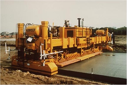
Figure 9-31. Slip-form paver.
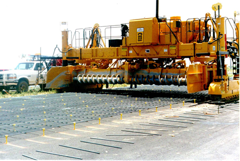
Figure 9-32. Slip-form paver with two augers (idle).
A machine with two tracks is steered by varying the speed of the tracks from one side to the other side. The bigger machines with four tracks, two tracks on each side, are stirred by pivoting each track, much like the front wheels on a car. The tracks can either ride on the base or on a previously placed pavement. Figure 9-33 shows a paver machine on tracks.
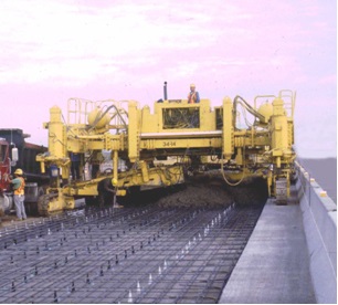
Figure 9-33. Paver machine on tracks.
The base should extend out, past the paver’s tracks, to give adequate support for the machine. This is illustrated in Figure 9-34. The track path should be level and clean to allow for a smooth concrete surface. Do not force the grade control sensor to make up for trash, such as spilled concrete or tie bars, in the track path.
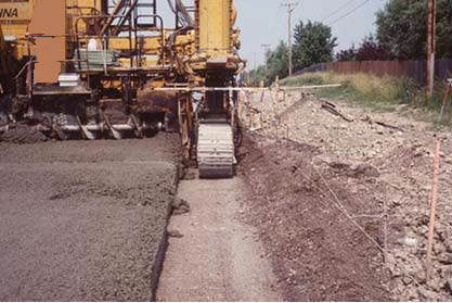
Figure 9-34. Track path.
6.3.3 Vertical Alignment Control
Usually, slip-form pavers have an electronic sensor system or equivalent to provide grade control. Figure 9-35 and Figure 9-36 show examples of such sensors. Sensors come in both electronic and hydraulic models. The electronic sensors work better.
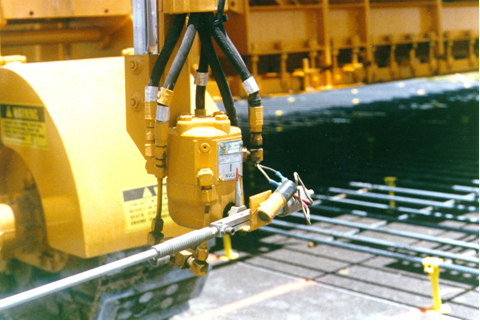
Figure 9-35. Electronic sensor.
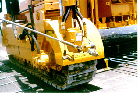
Figure 9-36. Electronic sensor.
The grade control sensors, one on each side of the paver, have wands that ride on the bottom of a guide wire that adjusts the height of the entire machine by raising or lowering the vertical hydraulic cylinders on each side of the machine. Figure 9-37 shows vertical and horizontal sensors. The guide wire is supported and tensioned to prevent any measurable sag. Figure 9-38 shows the side view of an idle paver. Notice the two hydraulic cylinders on the side of the paver (right side of Figure 9-38). Figures 9-39 and 9-40 show the guide wire controls.
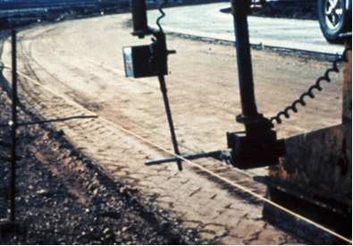
Figure 9-37. Horizontal and vertical sensors.
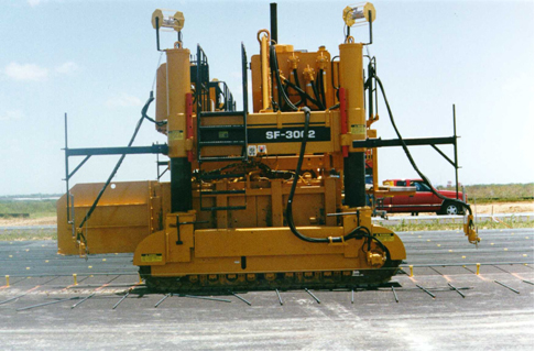
Figure 9-38. Side view of an idle paver.
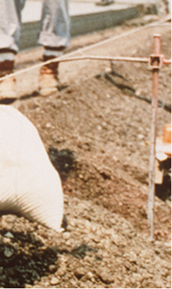
Figure 9-39. Guide wire controls.
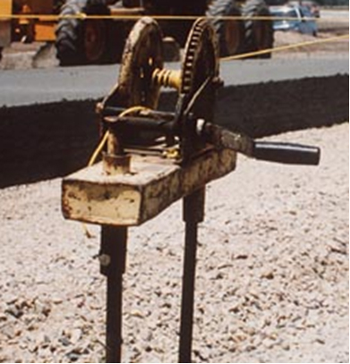
Figure 9-40. Another view of guide wire controls.
6.3.4 Horizontal Alignment
The alignment or steering of the paver can be either sensor-controlled or operator-steered.
6.3.5 String-less Concrete Paving
The following information is taken from the FHWA Concrete Pavement Road MAP. Conventional concrete paving with a slip-form paver requires the installation of a stringline and support posts adjacent to the roadway to establish the correct pavement alignment and profile. The stringline adds several additional feet (+/- 6 ft.) of required clearance to the paving envelope, which is already wider than the pavement due to the tracks of the slip-form paver. In addition, the stringline becomes an obstacle for equipment, concrete delivery trucks, and finishing crews. If equipment access across the stringline is required, the stringline must be lowered and reset, resulting in delays and introducing the potential for errors.
String-less paving is a technology that eliminates the installation and maintenance of stringlines and has the potential to decrease the need for surveying and increase the smoothness of the pavement profile. The benefits that can result from string-less paving include increased production, decreased construction time, and reduced potential for errors.
Several companies have developed string-less equipment control and guidance systems using technologies such as global positioning systems (GPS), robotic total stations, and laser positioning. String-less technology replaces the traditional stringlines with an electronic tracking process that controls the horizontal and vertical operation of the slip-form paver. The construction industry has been using string-less technology for elevation and steering control of equipment for a number of years. To date, the extensive use of this technology has been applied to grading operations. However, string-less paving is an emerging technology for concrete paving because it has the potential to allow contractors and owner/agencies to receive production benefits (e.g., reduced survey costs, fewer construction hours) while still meeting smoothness requirements. Figure 9-41 shows the string-less paving machine.
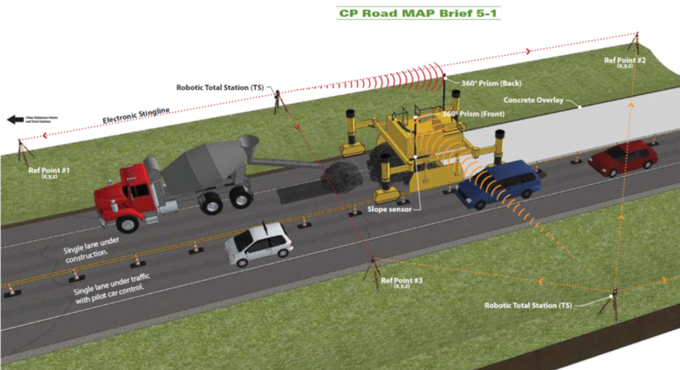
Figure 9-41. String-less paving equipment.
Contractors using string-less paving equipment are still required to establish control points at maximum intervals of 500 ft. and use the control points as reference.
6.3.6 Paver’s Forward Speed
The speed the paver moves forward is controlled by the operator. The speed should be as uniform as possible, but should vary with the rate of concrete delivery so that complete stops are held to a minimum. The paver speed is up to 20 ft. per minute.
If the paver stops moving forward, the vibrators must be turned off within 5 seconds. Continued running of the vibrators will result in segregation of the concrete, forcing water and fines to the surface.
6.3.7 Augers
Rotating the augers moves the concrete sideways across the entire lane being paved. The augers are controlled by the operator and can be turned either clockwise or counterclockwise as needed. Figure 9-42 shows a close-up of an auger.
The augers on the spreader of a paving machine help distribute the concrete over the width of the pavement placement ensuring that a uniform head of concrete is maintained across the pavement width and extending well above the vibrators. This overburden over the vibrators helps direct the energy from the vibrators downward into the concrete pavement and helps ensure proper consolidation of the concrete. Figure 9-43 shows the spreading of the concrete.
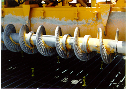
Figure 9-42. Close-up of an auger.
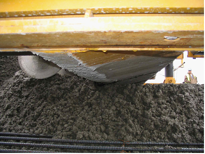
Figure 9-43. Auger and strike-off spreading the concrete.
6.3.8 Vibrators
The frequency in air of the immersion vibrator units shall not be less than 8,000 cycles per minute. Figure 9-44 shows immersion of vibrators. Handheld vibrators are driven by an electric motor.
Vibrators on a slip-form paver are hydraulically driven. Figure 9-45 shows the underside of a slip-form. Going from right to left, observe the:
- augers,
- strike-off screed,
- vibrators,
- finishing screed, and
- pan float.
Vibrators need to be mounted high enough that they will not snag any of the reinforcing steel. An isolated streak in the concrete pavement behind the paving machine may indicate that there is a non-working vibrator.
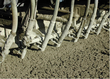
Figure 9-44. Immersion vibrators.
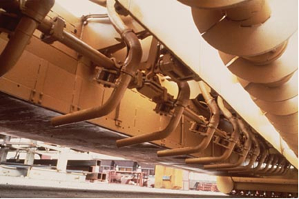
Figure 9-45. Underside of slip-form paver.
Figure 9-46 shows the normally recommended vibration position. The paver is moving to the left. A concrete head or surcharge should be maintained over the vibrators during placing operations. The vibrators must be turned off whenever the forward motion of the paver is stopped. Figure 9-47 shows the vibrated zones.
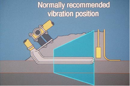
Figure 9-46. Normally recommended vibration position.
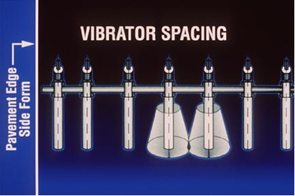
Figure 9-47. Drawing showing the vibrated zone.
No vibrator streaks or trails should be apparent behind the paver. Figure 9-48 shows unacceptable vibrator streaks. Here, the vibrators are not vibrating enough. Because of this, the vibrators are plowing a trail instead of vibrating the concrete.
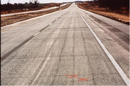
Figure 9-48. Unacceptable – vibrator streaks.
6.3.9 Pan Float
After screeding, the concrete surface is finished with a pan float that further smooths and consolidates the concrete. Pan floats are solid plates anywhere from 18 to 60 in. wide and slightly narrower than the pavement width. Figure 9-49 shows pan floats on an idle paver.
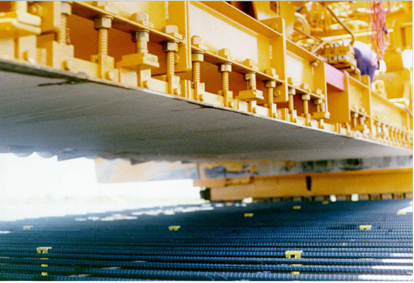
Figure 9-49. Looking up at a pan float on an idle paver.