7.3 Construction Joints
Construction joints can be longitudinal or transverse. A transverse construction joint is formed when the paving operation is stopped because of the end of the workday or because of a mechanical breakdown. A longitudinal construction joint is formed when two adjoining lanes are placed with separate concrete placements.
For transverse construction joints, provide a bulkhead (header) that is of sufficient cross sectional area to prevent deflection, accurately notched to receive the load transmission devices, and shaped accurately to the cross section of the pavement (see Figure 9-75).
For CPCD, install a transverse construction joint either at a planned transverse contraction joint location or mid-slab between planned transverse contraction joints. Install tie bars of the size and spacing used in longitudinal joints for mid-slab transverse construction joints. For CRCP, additional longitudinal steel is required (see Figure 9-76). Protect the reinforcing steel immediately beyond the transverse construction joint from damage, vibration, and impact. Splicing of longitudinal steel is not allowed within 10 ft. of a transverse construction joint.
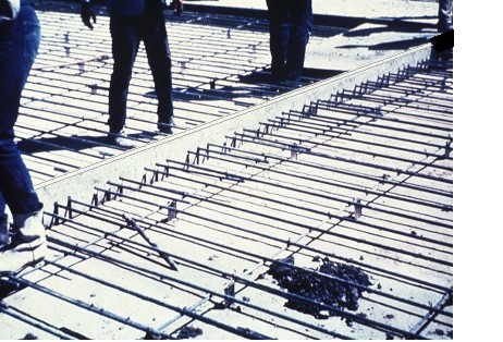
Figure 9-75. Bulkhead (header).
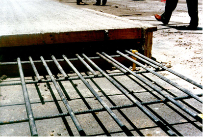
Figure 9-76. Additional steel is required at header.
For longitudinal construction joints, the short pieces of reinforcing steel across the joints are called tie bars. The tie bars keep the two adjoining slabs from pulling away from each other and keep the surface across the joints flat. In Item 360, either single piece tie bars or multiple piece tie bars are allowed at the longitudinal construction joints. The detailed requirements for tie bars, such as length, size, and spacing, are shown in the Standards.
One-piece tie bars may be used when they do not interfere with traffic or construction conditions. The tie bars are inserted manually or mechanically in the concrete that is still confined by the slip-form paver. Larger finishing machines have the capacity to mechanically insert the tie bars evenly with little disturbance to the plastic concrete. When inserting one piece tie bars, caution is needed to avoid hitting the reinforcing mat with the tie bars. It is recommended to insert tie bars a few inches away from the transverse bar locations to avoid displacing the mat. Insertion by hand often causes the edge of the plastic concrete to drop down and requires constant remedial work. Figure 9-77 shows a surface drop down due to hand insertion.
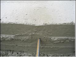
Figure 9-77. Surface drop down due to hand insertion.
Check tie bar insertion depth and locations during paving operations to ensure proper placement. Care must be taken to prevent any movement of the tie bars after placement. Figure 9-78 shows an example of a wood side form at a transverse construction joint. The tie bars at this side form location were not inserted into the plastic concrete. A hole will be drilled and filled with epoxy grout for each tie bar not originally placed.
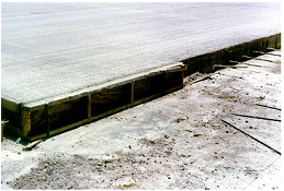
Figure 9-78.Wood side form at a transverse construction joint.
Multiple piece tie bars are threaded in the middle to allow the two halves of the tie bar to be separated and then reconnected prior to the casting of the adjacent pavement. Finish multiple piece tie bar assemblies from the approved list of DMS – 4515, “Multiple Piece Tie Bars for Concrete Pavements.”
In the past, bent tie bars were commonly used to keep the tie bars from interfering with traffic or construction. After the concrete set, the bent tie bars were straightened to the proper position. This practice is no longer allowed, since there were problems due to the weakening of the tie bar which leads to steel rupture and lane separations.
Figure 9-79 shows the spacing of the transverse steel and the spacing of the tie bars in a CRCP section.
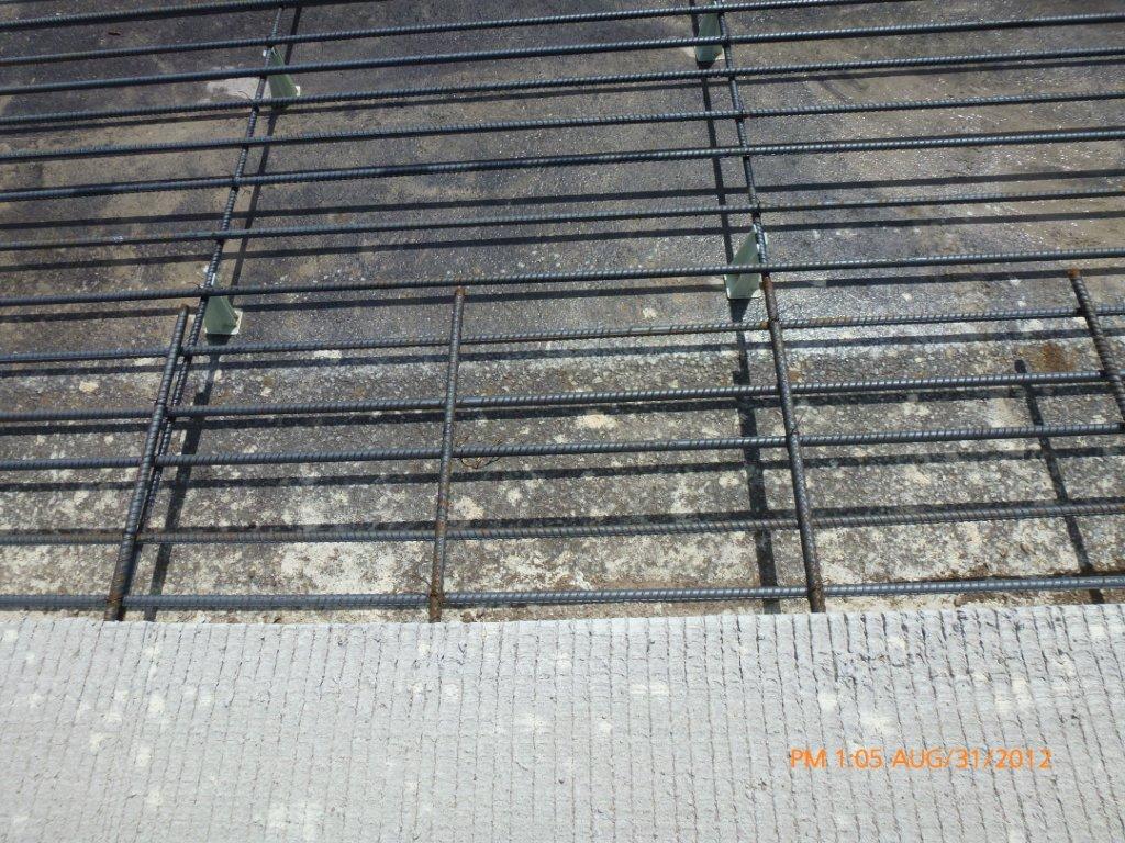
Figure 9-79. Tie bars.
Tie bars are also used in plain jointed concrete pavement. When these tie bars are used to connect two lanes, or a lane and shoulder, the tie bar may be mechanically inserted by the paving machine into the fresh concrete ahead of the float, or it may be held in position by support devices. Unlike CRCP, there is not an available mat of steel reinforcement that can be used to position and secure the tie bars. Each tie bar will need to be separately supported and held in position by stakes or pins driven into the base. These supports need to be sturdy enough to hold the tie bar in position when concrete is placed and consolidated over it.
Tie bars are required at longitudinal widening joints for CRCP and CPCD. Provide #6 bars at 24 in. spacing for 8-in. and thicker slabs. Use #5 bars at 24 in. spacing for less than 8-in. thick slabs. Refer to the CRCP standard for the longitudinal widening joint details.
Mark the tie bar locations and drill holes into the existing concrete at least 10 in. deep. Use a drill bit with a diameter that is 1/8-in. greater than that of the tie bars. Figure 9-80 shows the drilling operation being performed at a widening joint. When manufacturer’s instructions are available, precisely follow the requirements for cleaning the holes as outlined. Clean the holes with a wire brush and compressed air to remove all the dust and moisture. Follow the epoxy manufacturer’s instructions to apply the epoxy. Insert the tip of the epoxy cartridge or the tip of the machine applicator to the end of the tie bar hole and inject Type III, Class C, epoxy to fill the entire hole, then insert the tie bars.
Demonstrate, through simulated job conditions, that the bond strength of the epoxy-grouted tie bars meets a pullout strength of at least 3/4 of the yield strength of the tie bar when tested in accordance with ASTM E 488, within the Epoxy manufacturer's recommended curing time. Increase embedment depth and retest when necessary to meet testing requirements. Perform tie bar testing before starting widening work.
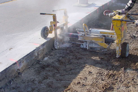
Figure 9-80. Marking and drilling holes at widening joint.