4.3 Falling Weight Deflectometer (FWD)
The falling weight deflectometer (FWD) is a trailer-mounted device that places an 11.8 in. (300 mm) diameter load plate in contact with the highway at each test location. The testing interval is set at 0.1 mi. (maximum) or a minimum of 30 locations per project. A load column above the load plate carries a stack of weights that are dropped to impart a load to the pavement similar to that imparted by a passing dual truck tire set. A series of seven geophones spaced away from the load plate at 12-in. increments measure the surface deflection, generating a “deflection bowl.” Measurements are generally acquired in the right wheel path of the outside lane. The latest upgrade to the FWD includes an 8th geophone mounted 12 in. from the load plate opposite sensor #2. This sensor facilitates evaluating load transfer across joints and cracks on rigid pavement. GPS coordinates are also automatically posted to the deflection file for each tested location.
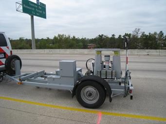
Figure 4-4. Falling Weight Deflectometer (FWD).
Figure 4-5. Falling Weight Deflectometer, detail view.
Where a divided roadbed exists, surveys should be taken in both directions if the project will include improvements in both directions. Some care in the placement of the load plate and sensors is required by the survey crew, especially where the highway surface is rutted or cracked. The load plate should lay on a flat surface; the load plate and all geophones should lie on the same side of any visible cracks. A human spotter should be used to ensure placement in these cases.
Temperature data collected at the time of testing is necessary for all flexible pavements since the modulus of bituminous materials is temperature-dependent. The FWD has a built-in thermocouple to measure ambient air temperature and an infrared sensor to measure surface temperature, and records these temperatures at each drop location. In addition, for pavements with bituminous surfaces at least 3.0 in. thick, in-pavement temperature measurements should be made at the beginning and end of each survey, at a minimum. Longer surveys or surveys made on days where rapid temperature changes occur will require temperature checks at additional intermediate locations. A portable drill with masonry bit can be used to accomplish this; holes are drilled to mid-depth or 3.0 in. maximum. Alternatively, surface temperatures measured by infrared devices can be made with correlations available for mid-depth temperature estimation. The
can be used for this purpose. This program is available through the department’s MNT intranet page, under Engineering Applications.
Liberal use of comments placed in the FWD data file at the time of data collection is encouraged. Comments pertaining to offset from reference markers and bridge abutments, or proximity to patches, cracks, etc., are all important documentation for the individual evaluating the data. Interpretation of collected deflection data can be based on simple comparison of the normalized (for load) maximum measured deflections, or can be much more rigorous, for example, by using backcalculation methods or evaluation of deflection time-histories. Detailed discussion on the backcalculation methodology of layer moduli for flexible pavements is found in Chapter 5, Section 4,
Description of the FWD with conceptual discussion on basic operation is given in the
Flexible Pavement Rehabilitation Strategies training course
available through the department’s MNT intranet page, under
.4.3.1 Evaluating Deflection Data for Load Transfer on Rigid Pavements
Efficient load transfer across joints and cracks on rigid pavements is necessary for good performance. Deterioration of cracks and joints through spalling, widening, ruptured steel, erosion of subbase support, and moisture and incompressible materials intrusion will tend to reduce the load transfer efficiency over time. Evaluating the existing load transfer efficiency is necessary to formulate an appropriate rehabilitation strategy. For example, if the level of efficiency is above 70%, an HMA overlay may be an appropriate rehab strategy. Load transfer in concrete slabs is significantly influenced by ambient temperatures; higher temperatures will cause cracks and joints to close, thereby improving aggregate interlock and load transfer. For comparability and veracity of results, all testing should be accomplished at relatively steady temperatures below 80°F. In a typical load transfer setup with the FWD, the FWD is initially positioned with the load plate edge tangent to the crack or joint to be tested, with the W2 sensor positioned on the opposite side of the joint or crack as shown in Figure 4-6.
Figure 4-6. FWD setup to measure joint load transfer.
The AASHTO ’93 Design Guide defines load transfer efficiency as:
Where d
je
is the joint efficiency; du
is the deflection on the unloaded side; and dl is the deflection on the loaded side. First, the deflection at W2 is du
, measuring efficiency from the approach slab perspective. Then, the FWD is pulled forward with the load plate tangent to the joint from the departure slab perspective, and W8 is du
. W1 will be the dl
in both cases. Whichever measurement indicates the lower efficiency should be used for rehab considerations.Another methodology for determining load transfer efficiency is to use deflections at the crack or joint compared to that at center slab. First, the FWD is positioned at center slab (away from working joints/cracks) and deflection measurements at the W1 and W2 sensors are noted (W1
cs
and W2cs
, respectively). Then, the FWD is moved forward to the joint to be evaluated and the load plate is positioned tangent to the joint on the same slab, with the W2 on the opposite side of the joint as in the AASHTO procedure. Deflection measurements at the W1 and W2 sensors are noted (W1jt
and W2jt
, respectively). Load transfer efficiency is determined as:
Similarly, the evaluation can be performed with the load plate tangent to the joint on the adjacent slab, where the W8 sensor will be used in the above formula in place of the W2jt reading.
The customary Dynatest FWD data file (.fwd file extension) used by TxDOT for backcalculation will only report data for the first seven sensors. However, current FWD survey data protocol saves all sensor data in a small MS Access database, from which data may be extracted to conduct load transfer efficiency calculations.