4.4 Dynamic Cone Penetrometer (DCP)
This portable device complies with ASTM D 6951 and consists of a 2-piece rod; the lower rod is about 39 in. long (1 m) and is fitted with a replaceable cone tip at the penetration end and an anvil at the upper end. The anvil houses a threaded or shear pin receptacle for attaching the upper rod. The upper rod carries the 17.6-lb. sliding hammer and has a handle for steadying the device during testing. The hammer free-fall distance on the upper rod is 22.6 in.
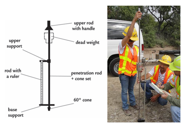
Figure 4-7. Dynamic Cone Penetrometer (DCP).
4.4.1 DCP Operation Instructions
The operator drives the DCP tip into the soil by lifting the sliding mass (hammer) with one hand to the handle then releasing it. The other hand holds the instrument by the handle to maintain an approximate vertical position. If a bound layer (HMA, PCC, cement-stabilized base) is present above the non-bound layers, a 1.25 in. hole should be first bored through the bound layer(s).
4.4.2 DCP Readings and Data Collection
An initial depth reading is made using a measuring stick/tape between the bottom of the sliding mass and a stationary surface (pavement surface, ground level, etc.). The total penetration for a set of blows is measured and recorded by an assistant. A plot of depth vs. cumulative blows is generated, and a trend line is fitted to the data points for each tested layer. The penetration rate in mm/blow is determined as the slope of the trend line.
A separate trend line should be generated for each layer containing only data points measured in that layer. Dividing the data into discrete segments in this manner ensures that only valid data points can influence the trend line's slope.
The number of blows in a set can vary; for softer soils, 1-3 blows may be a set; whereas, for stiffer soils, 5-10 blows may be a set. Some soils may be so stiff that little to no penetration is recorded in a given set. Results of testing in flexible base materials with larger aggregates can often be invalidated when the cone attempts to drive an aggregate through the base material matrix. Under these circumstances, it is better to halt testing and bore/drill down to a lower level, or restart the test adjacent to the initial location. Any time drilling is done before the start of a DCP test, the first data point should be at the actual start depth and the person processing the data will not include the surface (zero depth) as a data point, since this would invalidate the penetration rate (mm/blow) calculation.
At the conclusion of the test, the instrument is extracted by tapping the mass upward (vertically, avoiding an arc) against the handle or by using a jack attached beneath the anvil. Both methods have some risk of damage to the instrument; in softer soils, when using a disposable cone, tapping the mass against the handle is the most expeditious method.
The Army Corps of Engineers has developed a number of correlations relating rate of penetration to soil stiffness in terms of California Bearing Ratio (CBR). For most applications, the following relationship is adequate for approximating in situ stiffness.
CBR = 292/PR
1.12
Where:
- CBR = California Bearing Ratio,
- PR = penetration rate, mm/blow.
This relationship has been further correlated to elastic modulus (E) using the relationship:
E = 2550
x CBR
0.64
Where:
- E = elastic modulus.
Plots can be made to show the relationship of stiffness with depth. This procedure is useful for determining the effective depth of a granular base, the effectiveness of lime stabilized subgrade, or whether there are soft pockets of material with depth. Visual examination of the DCP shaft, once extracted, can also reveal the presence of free moisture. Basic operation and example problems are presented in the
Flexible Pavement Rehabilitation Strategies training course
.