6.4 Designing a Perpetual Pavement Using FPS21
A summary of the steps to design perpetual pavement using FPS 21 follows.
Step | Action |
|---|---|
1 | Pavement design Type 7 (User Defined) is recommended for this type of structure. |
2 | Select a 30-yr. analysis period. |
3 | Use a confidence level of ‘C’ (95%). |
4 | Use lane distribution reduction factors when three or more lanes are planned in one direction to adjust the 20-yr. cumulative 18-kip ESALs. |
5 | Enter the 20-yr. cumulative ESALs (or adjusted ESALs) in the 18-kip ESAL field. |
6 | Select a “time to first overlay” of 15 yr. |
7 | Follow general guidelines for all other inputs. Note elevated moduli values are permitted for all HMA layers based on total thickness. Select the red arrow button to run the design. |
Steps 1-3:
Use pavement design Type 7 for this type of structure since perpetual pavements typically have more than 4 unique layers. Careful attention is emphasized for the selection of structural layers as recommended above under Section 2, Types of Flexible Pavements
. Select a 30-yr. analysis period. The analysis period will not be critical, since staying reasonably below the limiting strain criteria specified above is the ultimate goal. However, just meeting the criteria does not ensure adequate reliability (i.e., just meeting the 70 µ-strain criterion could mean a high probability of failure when not accounting for poor design, material variability, or construction practices). Set the FPS confidence level to ‘C’ (95%). This confidence level is not tied to the limiting strain criteria, but is useful in ensuring a reasonable beginning thickness to evaluate further.Steps 4 and 5
: Use lane distribution reduction factors when three or more lanes are planned in one direction. Adjust the 20-yr. cumulative ESALs, if needed, with an appropriate reduction factor; then enter the adjusted 20-yr. ESALs into FPS. The FPS program converts the 20-yr ESALs to 30-yr ESALs for the selected analysis period. Step 6:
Select a minimum “time to first overlay.” Fifteen years is recommended because this time frame will usually allow development of a structure of sufficient depth to meet the limiting strain criteria and still ensure a reasonable reliability. Establishing a “time to first overlay” may not appear to be consistent with “perpetual” design. Actually, the performance module within FPS 21 is inconsistent with perpetual design. The FPS-calculated overlay will not be a structural requirement, but should reasonably mimic an almost certain requirement for “surface renewal” to mitigate the effects of surface wear, oxidation, top-down cracking, etc.Step 7:
Follow general guidelines for all other inputs, with particular attention to serviceability indices and material moduli. Ensure a permanent foundation layer that accounts for environmental variability (including poor soils and moisture fluctuation) is included in the design. Select the red arrow
button to run the design.Depending on the thickness ranges selected, the resulting designs may indicate a requirement for an overlay prior to the end of the
analysis
period. (NOTE: Analysis period is not entirely pertinent to the development of a perpetual design in FPS, but serves as a rough gauge/reminder that one or more surface renewals will be needed over the design life.) Conduct a design check of the limiting strain criteria by activating the FPS 21 mechanistic check. Figure 5-6 shows a typical perpetual pavement setup in the mechanistic check input screen. Ensure that the horizontal red arrow tensile strain indicator symbol is placed at the lowest HMA interface by dragging it into place. The “vary thickness” green sensitivity button shall be dragged adjacent to the layer that the designer would most likely change the thickness of to optimize the design.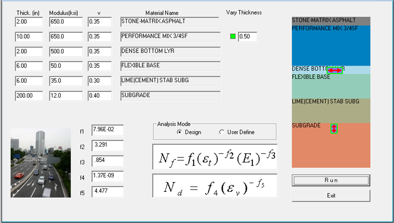
Figure 5-6. Mechanistic Check Input Screen.
By selecting the run button on the input screen, the mechanistic check output screen must show strain results below the limiting strain thresholds previously cited for bottom-up fatigue cracking and compressive failure of the subgrade (rutting) for the design to be valid. Also, the check will report “unlimited” fatigue and rutting life (> 150 million ESALs), as shown in Figure 5-7 below. For a thorough discussion on the use of the FPS Mechanistic Check feature, refer to the
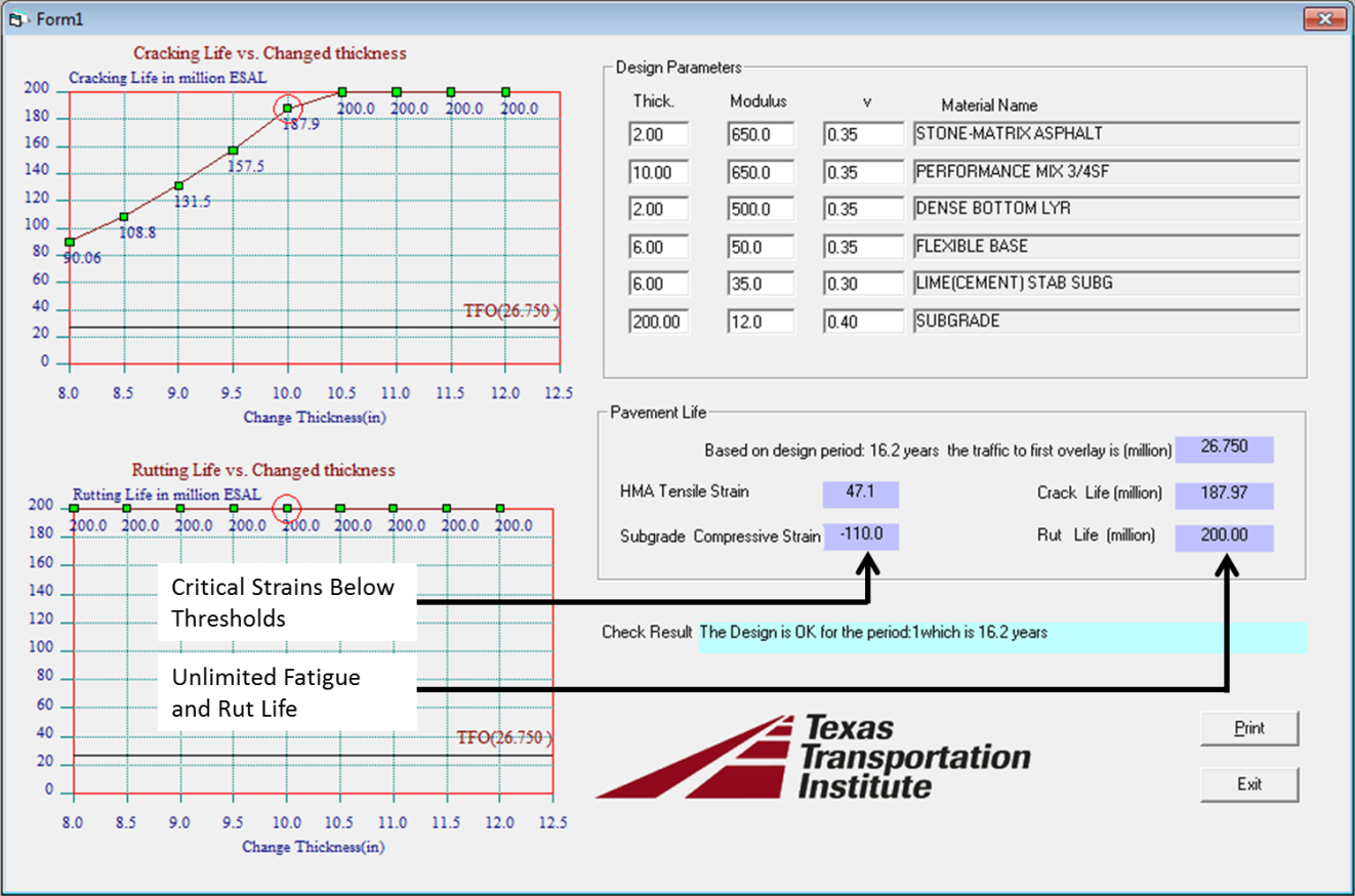
Figure 5-7. Mechanistic Checks Output Screen.