5.2 Pavement Widening
Widening is conducted to increase the flow capacity of the highway or to improve safety aspects, such as the inclusion of shoulders, turning bays, etc. Consideration shall always be given to maintaining the original cross section for the widened portion. This serves two purposes:
- it maintains uniformity in the section which facilitates future evaluation and rehabilitation options for the section as a whole, and
- it maintains subsurface drainage patterns which are essential to preventing trapped moisture.
Exceptions to this philosophy are generally related to poor performance in the existing section or the desire to expedite construction of the widened section to minimize interference with traffic.
Where traffic control can be facilitated, reworking/widening [add-rock if needed] of the pavement section full-width yielding an upgraded, uniform full-width section can often be obtained for a nominal additional cost over more problematic [poor performing] "scab-on" techniques. Consideration of this technique may be most appropriate for narrower or shoulder widening jobs.
In addition to cross section considerations, full lane-width widening will entail a full-depth joint that is unavoidably a weakened interface in the structure. Compaction against the vertical plane of the old structure will be more difficult to achieve than with full-width construction. Placement of this joint as far from the wheel path as possible will improve performance. Also, applying a final HMA overlay across the entire section with the overlay joint offset by 6-12 in. from the underlying vertical interface will improve the impermeability of the interface over the short term.
The underlying vertical interface at the widening will usually cause reflective cracking through to the surface. An aggressive crack sealing program will limit the amount of precipitation runoff from entering into the structure. Consideration shall also be given to using geotextiles/stress absorbing membrane interlayer (SAMI) over the widening joint prior to applying the full-width overlay as a means to delay reflective cracking.
Widening a 2-lane structure for the purpose of developing a Super2 or 4-lane cross section will entail additional considerations for cut locations and shoulder structural analysis when the existing shoulder may form part of a new driving lane. When the shoulder is to form part of a new lane, non-destructive surveys using the falling weight deflectometer (FWD) are essential. In addition, ground penetrating radar (GPR) may prove to be a useful preliminary survey tool to determine whether the shoulder matches the current driving lane in structure. Recommendations for pavement cut locations for Super2 construction are shown in Figure 5-2.
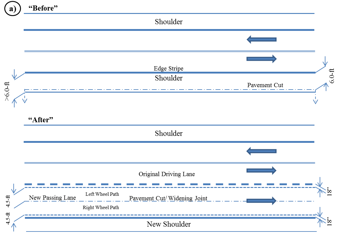
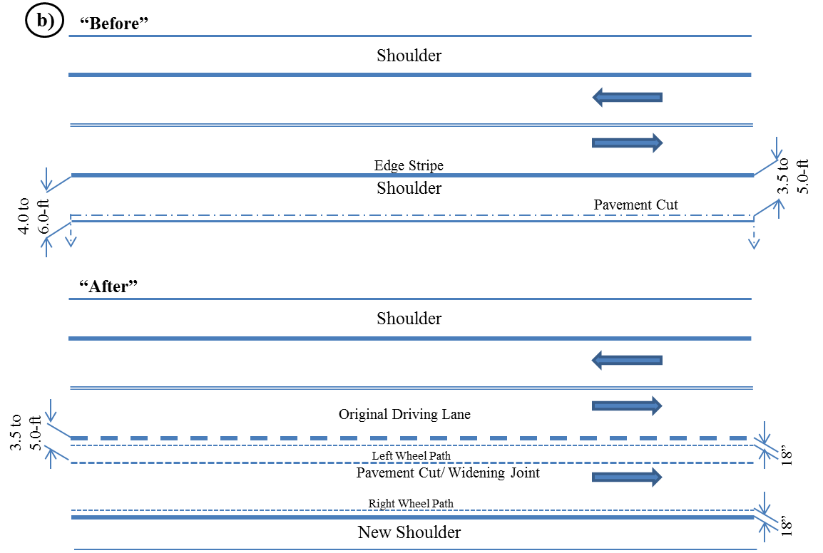
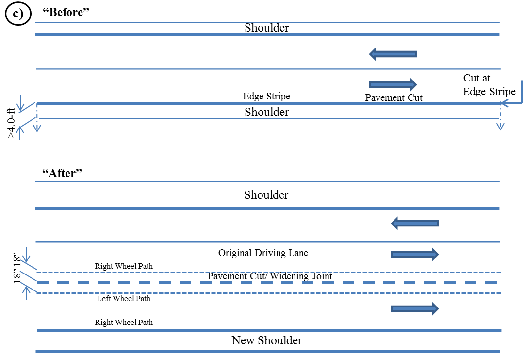
Figure 5-2. Recommended Widening Joint Location: a) 12.0-ft. Lanes, Original Shoulder > 6.0-ft. width, b) 12.0-ft. Lanes, Original Shoulder 4.0- to 6.0-ft. width, and c) 12.0-ft. Lanes, Original Shoulder < 4.0-ft. width.
5.2.1. Recommendations for Similar Cross Section Widening Strategies
The objective will be to match as close as practical the same cross section and materials in the widened section as were used in the original section.
5.2.1.1 Unbound Granular Base Sections
Other considerations are:
- Treatment of the subgrade under the widened location. This may serve to reduce moisture fluctuations at the new pavement edge which, in turn, should reduce potential for longitudinal edge cracking. An alternative may be to use geogrids at the subgrade/base interface. Treatment should be accomplished below the level of the old flex base.
- When milling any HMA to the outside of the existing lane, also remove an extra 12.0 in. to the inside of the existing lane edge (stripe). The object is to offset the HMA joints above the widening interface.
- Selection of the new flexible base material should be based on laboratory evaluation of both new and existing materials to compare the moisture susceptibility of each. Preferably, these should be about the same. A material that is more highly moisture-susceptible may draw moisture from both the original section and from outside the structure. A material that is less moisture-susceptible may send moisture into the original base, particularly during the initial curing process.
- Apply level-up to match original HMA surface elevation. Make repairs to original surface as necessary. Apply reflective crack retardant (geotextile, SAMI), if desired.
- Apply overlay across full section. Final longitudinal mat joints should be placed at lane stripes when used.
- Ensure ditch lines are sufficient to prevent hydraulic backflow into the pavement structure. Figure 5-3 depicts an example of an unbound base section.
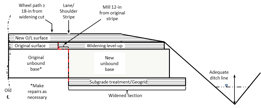
Figure 5-3. Unbound base sections.
5.2.1.2 Bound Base Sections
Other considerations will closely parallel those cited for the unbound base situation. If an original bound base is cement-treated material, there are cases when it may be preferable to use full-depth HMA for the widening to expedite construction. This strategy should not cause subsurface moisture flow problems (“bath tub” effect) when the cement treated base is not itself moisture-susceptible. Laboratory evaluation of core samples will reveal the degree of moisture susceptibility of the existing base.
5.2.2 Recommendations for Dissimilar Cross Section Widening Strategies
This widening strategy is not encouraged because it often results in lateral subsurface drainage restrictions (see Figure 5-4 “bath tub” effect). If it was possible to guarantee that no moisture would accumulate beneath the surface of the original structure, this type of widening would be easier to endorse.
Areas of the state that experience low rainfall and deep water tables may experience better performance with this type of widening strategy. If this type of widening is considered in wetter areas, consideration should be given to installing subsurface drainage at the widening interface, with laterals to the ditch line (Chapter 2, Section 8). Unfortunately, this remedy is generally counter to expediting construction. Sources of in-pavement moisture accumulation are shown below.
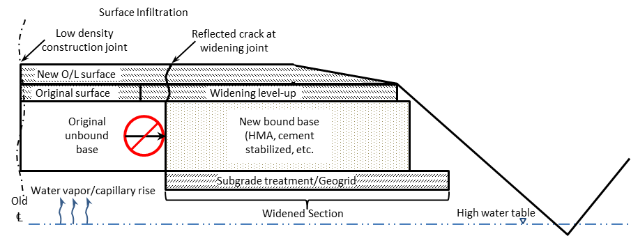
Figure 5-4. In-pavement moisture accumulation, resulting in “bath tub” effect.