8.5 Compaction Equipment
Compaction equipment compacts the HMA by two principal means:
- By applying its weight to the HMA surface and compressing the material underneath the surface contact area. Since this compression will be greater for longer periods of contact, lower equipment speeds will produce more compression. Obviously, higher equipment weight will also increase compression.
- By creating a shear stress between the compressed material underneath the surface contact area and the adjacent uncompressed material. When combined with equipment speed, this produces a shear rate. Lowering equipment speed can decrease the shear rate, which increases the shearing stress. Higher shearing stresses are more capable of rearranging aggregate into more dense configurations.
These two means of densifying HMA are often referred to collectively as “compactive effort." This section discusses the paver screed, the steel wheeled roller (both static and vibratory), and the pneumatic tire roller as they apply to HMA compaction. 'Compaction Sequence' discusses how each one of these pieces of compaction equipment work together in a typical construction scenario. This subsection covers:
- the paver screed,
- steel wheel rollers (including vibratory rollers),
- pneumatic tire rollers.
8.5.1 Paver Screed
The paver screed has previously been discussed in 'Screed.' Of additional note here is that approximately 75 to 85% of the theoretical maximum density of the HMA will be obtained when the mix passes out from under the screed (TRB, 2000).
8.5.2 Steel Wheel Rollers
Steel wheel rollers are self-propelled compaction devices that use steel drums to compress the underlying HMA. They can have one, two, or even three drums, although tandem (2 drum) rollers are most often used. The drums can be either static or vibratory and usually range from 86 to 215 cm (35 to 85 in.) in width and 50 to 150 cm (20 to 60 in.) in diameter. Roller weight is typically between 0.9 and 18 tonnes (1 and 20 tons) (see Figure 6-56 and Figure 6-57).
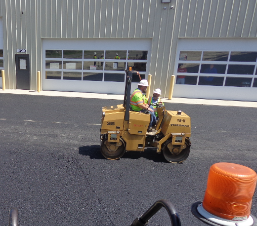
Figure 6-56. Small Static Steel Wheel Roller (1.45 tons 34-inch wide drum). © Copyright 2006 University of Washington
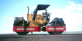
Figure 6-57. Large Vibratory Steel Wheel Roller (18.7 tons 84-inchwide drum). © Copyright 2006 University of Washington
In addition to their own weight, some steel wheel rollers can be ballasted with either sand or water to increase their weight and thus, compactive effort. Although this ballasting is a fairly simple process (see Figure 6-58), it is usually done before rolling operations start and rarely during rolling operations. Since asphalt cement binder sticks to steel wheels, most steel wheel rollers spray water on the drums to prevent HMA from sticking, and are equipped with a transverse bar on each drum to wipe off HMA. Note, however, that this water will cool the HMA and can reduce the time available for compaction.
Figure 6-58. Filling up with water. © Copyright 2006 University of Washington
8.5.3 Vibratory Steel Wheel Roller
Some steel wheel rollers are equipped with vibratory drums. Drum vibration adds a dynamic load to the static roller weight to create a greater total compactive effort. Drum vibration also reduces friction and aggregate interlock during compaction, which allows aggregate particles to move into final positions that produce greater friction and interlock than could be achieved without vibration. Roller drum vibration is produced using a rotating eccentric weight located in the vibrating drum (or drums), and the force it creates is proportional to the eccentric moment of the rotating weight and the speed of rotation (TRB, 2000). Operators can turn the vibrations on or off and can also control amplitude (eccentric moment) and frequency (speed of rotation). Vibration frequency and amplitude have a direct effect on the dynamic force (and thus the compactive force) as shown in Table 6-5:
Parameter | Typical Values | Effect on Dynamic Force |
|---|---|---|
Frequency | 1,600 to 3,600 vibrations per min |  |
Amplitude | 0.01 to 0.04 in. |  |
The ideal vibratory frequency and amplitude settings are a compromise based on desired mat smoothness, HMA characteristics, and lift thickness. Low vibration frequencies combined with high roller speeds will increase the distance between surface impacts and create a rippled, unsmooth surface. In general, higher frequencies and lower roller speeds are preferred because they decrease the distance between surface impacts, which:
- increases the compactive effort (more impacts per unit of length), and
- provides a smoother mat.
The recommended impact spacing is (10 – 12 impacts/ft.). Table 6-6 shows basic guidance for vibratory settings.
HMA/Mat Characteristics | Frequency | Amplitude |
|---|---|---|
Thin Lifts (< about 1.25 in.) | Operate in static mode. Under vibratory mode, as the pavement increases in density, the drums may begin to bounce, which may cause the HMA to shove and become less dense. Also, some of the aggregates may be crushed. In some cases, vibratory mode may be allowed to obtain a smooth transition or joint density. | |
Lifts between 1.25 and 2.5 in. | High frequency | Low amplitude |
Lifts beyond 2.5 in. | High frequency | Higher amplitude |
Stiff (more viscous) HMA | High frequency | Higher amplitude |
As a general rule-of-thumb, a combination of speed and frequency that results in 30 – 35 impacts/m (10 – 12 impacts/ft.) is good. At 3,000 vibrations/min., that gives a speed of 2.8 – 3.4 mph.
When density is difficult to quickly achieve with a vibratory steel wheel roller, the tendency may be to increase vibratory amplitude to increase compactive effort. However, high amplitude is only advisable on stiff mixes or very thick lifts that can support the increased amplitude without fracturing the constituent aggregate particles. For typical mix types and lift thicknesses, a better solution is usually to maintain low amplitude vibrations and increase the number of roller passes at low amplitude.
Vibratory steel wheel rollers offer potential compaction advantages over static steel wheel rollers, but they also require the operator to control more compaction variables (amplitude, frequency, and vibratory mode use) and, in certain situations, they must be used with caution (e.g., over shallow underground utilities, in residential areas, thin overlays).
In general, steel wheel rollers provide the smoothest mat finish of all compaction equipment. When operated in the vibratory mode, they also provide substantial compactive effort.
8.5.4 Pneumatic Tire Rollers
The pneumatic tire roller is a self-propelled compaction device that uses pneumatic tires to compact the underlying HMA. Pneumatic tire rollers employ a set of smooth (no tread) tires on each axle; typically four on one axle and five on the other. The tires on the front axle are aligned with the gaps between tires on the rear axle to give complete and uniform compaction coverage over the width of the roller. Compactive effort is controlled by varying tire pressure, which is typically set between 60 psi and 120 psi (TRB, 2000).
Asphalt binder tends to stick to cold pneumatic tires but not to hot pneumatic tires. A release agent (like water) can be used to minimize this sticking; however, if asphalt binder pickup (the asphalt binder sticking to the tires) is not permanently damaging the mat, it is better to run the roller on the hot mat and let the tires heat up to near mat temperature. Tires near the mat temperature will not pick up an appreciable amount of asphalt binder. Insulating the tire area with rubber skirts or plywood helps maintain the tires near mat temperature while rolling (see Figure 6-59).
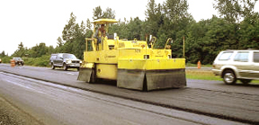
Figure 6-59. Pneumatic Tire Roller (notice rubber skirt insulation around tire area as well as tire marks left in the new mat in front of the roller). © Copyright 2006 University of Washington
In addition to a static compressive force, pneumatic tire rollers also develop a kneading action between the tires that tends to realign aggregate within the HMA. This results in both advantages and disadvantages when compared to steel wheel rollers:
- Advantages (Brown, 1984)
- They provide a more uniform degree of compaction than steel wheel rollers.
- They provide a tighter, denser surface, thus decreasing permeability of the layer.
- They provide increased density that many times cannot be obtained with steel wheeled rollers.
- They compact the mixture without causing checking (hairline surface cracks), and they help to remove any checking that is caused with steel wheeled rollers.
- Disadvantages
- The individual tire arrangement may cause deformations in the mat that are difficult or impossible to remove with further rolling. Thus, they should not be used for finish rolling.
- If the HMA binder contains a rubber modifier, HMA pickup (mix sticking to the tires) may be so severe as to warrant discontinuing use of the roller.
In summary, pneumatic tire rollers offer a slightly different type of compaction than steel wheel rollers. The arrangement of multiple tires on both axles serves to both compress and knead the mat, which may or may not be advantageous over steel wheel rollers.