4.12.6 Parallel Drainage Culverts
The inlet and outlet points of culverts handling drainage parallel to the travel lanes, such as at driveways, side roads, and median crossovers, are concerns in providing a safe roadside environment. Flow quantities for parallel drainage situations are generally low with drainage typically accommodated by a single pipe. The following guidelines apply to driveway, side road, and median crossover drainage facilities:
- Within the clear zone, there should be no culvert headwalls or vertical ends. Outside the clear zone, single pipe ends preferably should be sloped although not required.
- Where used, sloped pipe ends should be at a rate of 1V:6H or flatter. The sloping end may be terminated, and a vertical section introduced at the top and bottom of the partial pipe section as shown in .
- Median crossover, side road, and driveway embankment slopes should be 1V:6H maximum steepness, with 1V:8H preferred, within the clear zone dimensions.
- Where greater than 30-in diameter pipe ends are located within the clear zone, safety pipe runners should be provided with a maximum slope steepness of 1V:6H. Typical details for a driveway, side road, or median crossover grate are shown in . Cross pipes are not required on single, small (30-in or less diameter) pipes regardless of end location with respect to clear zone requirements; however, the ends of small pipes should be sloped as described above and appropriate measures taken to control erosion and stabilize the pipe end. Multiple 30-in pipes require cross pipes.
- The use of paved dips, instead of pipes, is encouraged particularly at infrequently used driveways such as those serving unimproved private property if adequate conveyance can be provided.
- For unusual situations, such as driveways on high fills or where multiple pipes or box culverts are necessary to accommodate side or median ditch drainage, the designer should consider the alternatives available and select an appropriate design.
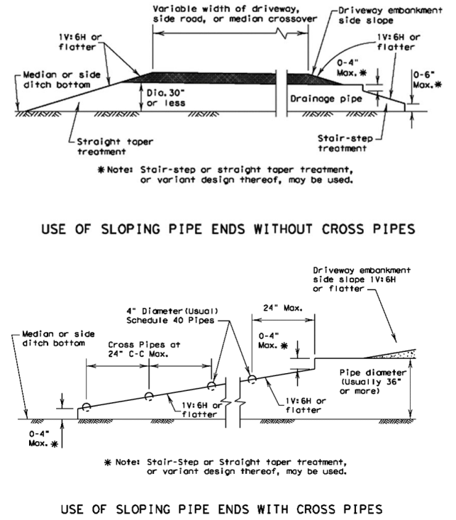
Figure 4-32: Sloping Pipe Ends