Guide Banks (Spur Dikes)
The twofold purpose of guide banks is to align flow from the floodplain with the waterway opening and minimize scour at the abutment by moving the scour-causing turbulence to the upstream end of the guide bank. Where the floodwater must flow along the embankment for more than 800 feet, guide banks should be considered. Figure 9-20 shows a typical plan form.
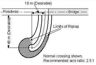
Figure 9-20. Typical Guide Bank
Guide banks are usually constructed of earthen embankment but are sometimes constructed from rock. The dike should be protected by revetment where scour is expected to occur, although a failure at the upstream end of a spur dike usually does not immediately threaten the bridge end.
Clearing around the end of the dike in wooded floodplains should be minimized to enhance the effectiveness. A drainage channel around the end of the dike for local drainage may induce turbulence from mixed flows. Instead, a small culvert through the dike will help minimize the turbulence of mixed flows from different directions.
The suggested shape of guide banks is elliptical with a major-to-minor axis ratio of 2.5:1. The suggested length varies with the ratio of flow diverted from the floodplain to flow in the first 100 feet of waterway under the bridge. The suggested shape is based on laboratory experiments, and the length is based on modeling and field data. The optimum shape and length may differ for each site and possibly for each flood at a site. However, field experience shows, however, that the recommended elliptical shape is usually quite effective in reducing turbulence. Should practical reasons require the use of another shape such as a straight dike, more scour may be expected at the upstream end of the guide banks. Guide banks can also be used at the downstream side of the bridge to help direct flow back into the overbanks.