Standard Step Backwater Method (used for Energy Balance Method computations)
Refer to Chapter 7 for the
. Figure 9-12 shows the relative location of section geometry for profile computations. B
d
and Bu
refer to the bridge geometry at the downstream and upstream inside faces, respectively.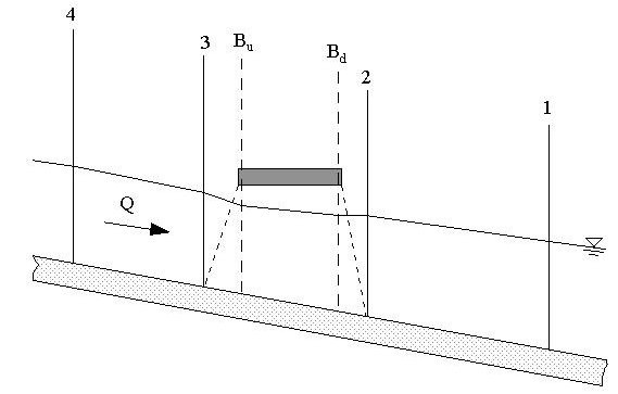
Figure 9-12. Relative Location of Section Geometry
- Solve the energy equation (step backwater) between cross section 2 and the downstream bridge face (Bd). Use the water surface at cross section 2 determined from the previous backwater profile computations.
- Proceed with the standard step backwater calculations from the downstream bridge face to the upstream face. Use the bridge geometry superimposed on cross sections 2 and 3 respectively.
- Approximate the effects of piers and impingement of flow on the lowchord by reducing the section area and increasing the wetted perimeter accordingly.
- Similarly, consider roadway overflow as open channel flow. Proceed with calculations from the upstream bridge face (Bu) to cross section 3.
- As indicated in the previous subsection, proceed with calculating the remainder of the bridge impact from cross section 3 upstream using step backwater calculations.
Under the right circumstances, you can consider the energy balance method for low flow and high flow.