Crossing Profile
The horizontal alignment of a highway at a stream crossing should be considered in selecting the design and location of the waterway opening, as well as the crossing profile. Every effort should be made to align the highway so that the crossing will be normal to the stream flow direction (highway centerline perpendicular to the streamline). Often, this is not possible because of the highway or stream configuration.
When a skewed structure is necessary, such as appears in Figure 9-9, the substructure fixtures such as foundations, columns, piers, and bent caps must be designed to offer minimum resistance to the stream flow .at flood stage. The channel may meander within the floodplain and cross under the roadway at an angle different from the floodplain. The bents and headers should be aligned to the stream flow at flood stage because most damage to the bridge happens at flood stage. Flood stage flows also carry the most amount of debris. Bents not aligned with the flood flow will become an obstruction to the flood flow and increase the risk of scour or other failure. The standard skew angles, 15º, 30º, and 45º should be used unless the flow volume or some other problem renders them impractical.
In spite of the flood flow orientation, bents should not be located in the low flow channel if at all possible. As the flow is most concentrated in the channel, the piers would be subject to the highest hydraulic forces. The placement would also increase risk of scour by creating eddies and turbulence, and may encourage drift buildup.
Additionally, relief openings should be provided at the approximate location of point A in Figure 9-9 to reduce the likelihood of trapped flow and to minimize the amount of flow that would have to travel up against the general direction of flow along the embankment.
With the configuration shown in Figure 9-9, the difference in water surface on either side of the embankment at points A and B will be higher than water surface differential through the opening. Relief openings at A and B will help minimize the differential.
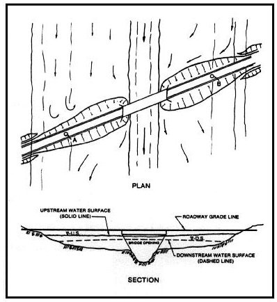
Figure 9-9. Skewed Stream Crossing and Water Surface Differentials