Velocity Control Devices
A velocity control device serves to effectively reduce an excessive culvert outlet velocity to an acceptable level. The design of some control devices is based analytically while, for others, the specific control may be unpredictable. Some velocity control devices are as follows:
- Natural hydraulic jumps (most control devices are intended to force a hydraulic jump) -- Most velocity control devices rely on the establishment of a hydraulic jump. Because a culvert being on a relatively steep slope usually results in excessive outlet velocity from the culvert, the depth downstream of the culvert exit is usually not great enough to induce a hydraulic jump. However, some mechanisms may be available to provide a simulation of a greater depth necessary to create a natural hydraulic jump.
- Broken-back culvert configuration -- One mechanism for creating a hydraulic jump is the broken back configuration, two types of which are depicted in Figure 8‑26 and Figure 8‑27. When used appropriately, a broken back culvert configuration can influence and contain a hydraulic jump. However, there must be sufficient tailwater, and there should be sufficient friction and length in unit 3 (see Figure 8‑26 and Figure 8‑27) of the culvert. In ordinary circumstances for broken back culverts, you may need to employ one or more devices such as roughness baffles to create a high enough tailwater.
- Sills -- The use of the sill is effective in forcing a hydraulic jump in culverts. One disadvantage of sills is the possible susceptibility for silting. Sills must usually be maintained frequently to keep it free of sediment deposition. Another disadvantage is the waterfall effect that they usually cause. Riprap should be installed immediately downstream of the sill for a minimum distance of 10 feet to protect features from the turbulence of the waterfall effect.
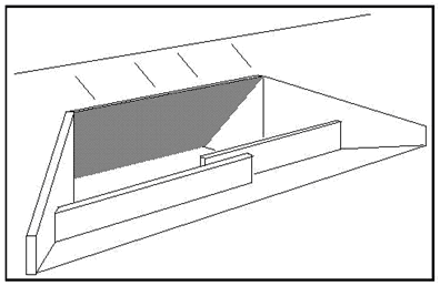 Figure 8-24. SillsRoughness baffles -- Roughness baffles, sometimes referred to as 'dragon's teeth', can be effective in inducing turbulence, dissipating energy, and reducing culvert outlet velocity (see Figure 8-25). Care must be taken in the design and placement of the baffles; if the baffles are too small or placed too far apart, they are ineffective. In addition, they may interfere with mowing operations around the culvert outlet. If these become damaged or broken from being hit by a mower, they are ineffective. To limit the amount of potential damage, baffles must be reinforced with rebar.
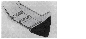 Figure 8-25. Roughness Baffles
- Energy dissipators -- An efficient but usually expensive countermeasure is an energy dissipator. Some energy dissipators have an analytical basis for design while others are intended to cause turbulence in unpredictable ways. With turbulence in flow, energy is dissipated and velocity can be reduced.
Other controls are described in the FHWA publication Hydraulic Design of Energy Dissipators for Culverts and Channels, HEC-14.
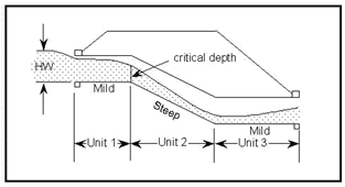
Figure 8-26. Three Unit Broken Back Culvert
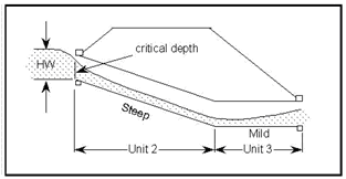
Figure 8-27. Two Unit Broken Back Culvert