Standard Step Procedure
The Standard Step Method uses the Energy Balance Equation,
, which allows the water surface elevation at the upstream section (2) to be found from a known water surface elevation at the downstream section (1). The following procedure assumes that cross sections, stationing, discharges, and n-values have already been established. Generally, for Texas, the assumption of subcritical flow will be appropriate to start the process. Subsequent calculations will check this assumption.
- Select the discharge to be used. Determine a starting water surface elevation. For subcritical flow, begin at the most downstream cross section. Use one of the following methods to establish a starting water surface elevation for the selected discharge: a measured elevation, the Slope-Conveyance Method to determine the stage for an appropriate discharge, or an existing (verified) rating curve.
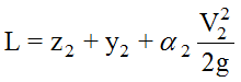
- Referring to and , consider the downstream water surface to be section 1 and calculate the following variables:
- z1= flowline elevation at section 1
- y1= tailwater minus flowline elevation
- α = kinetic energy coefficient (For simple cases or where conveyance does not vary significantly, it may be possible to ignore this coefficient.)
- From cross section 1, calculate the area, A1. Then use to calculate the velocity, v1, for the velocity head at A1. The next station upstream is usually section 2. Assume a depth y2at section 2, and use y2to calculate z2and A2. Calculate, also, the velocity head at A2.
- Calculate the friction slope (sf) between the two sections using Equation 7-5 and Equation 7-6:
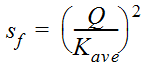 Equation 7-5.where:
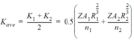 Equation 7-6.
 - Calculate the friction head losses (hf) between the two sections using
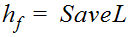 Equation 7-7.where:
- L = Distance in ft. (or m) between the two sections
- Where appropriate, calculate expansion losses (he) using Equation 7‑8 and contraction losses (hc) using Equation 7-9 (Other losses, such as bend losses, are often disregarded as an unnecessary refinement.)
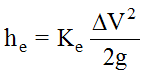 Equation 7-8.where:
- Ke= 0.3 for a gentle expansion
- Ke= 0.5 for a sudden expansion
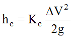 Equation 7-9.where:
- Kc= 0.1 for a gentle contraction
- Kc= 0.3 for a sudden contraction
- Check the energy equation for balance using Equation 7-10 and Equation 7-11.
 Equation 7-10.
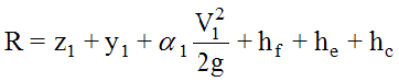 Equation 7-11.The following considerations apply:
- if L=R within a reasonable tolerance, then the assumed depth at Section 1 is okay. This will be the calculated water surface depth at Section 1; proceed to Step (9)
- if L≠R, go back to Step (3) using a different assumed depth.
- Determine the (dc) at the cross section and find the uniform depth (du) by iteration. If, when running a supercritical profile, the results indicate that critical depth is greater than uniform depth, then it is possible the profile at that cross section is supercritical. For subcritical flow, the process is similar but the calculations must begin at the upstream section and proceed downstream.
- Assign the calculated depth from Step (8) as the downstream elevation (Section 1) and the next section upstream as Section 2, and repeat Steps (2) through (10).
- Repeat these steps until all of the sections along the reach have been addressed.