Design Elements
Coastal structures can include roadways and bridges, but also include structures that promote coastal defenses with the objective of minimizing shoreline erosion or protecting against nearshore processes. Some of these coastal structures were discussed in Section 5. The general types and functions of coastal structures and roadway design, bridge design, and site-specific design conditions are discussed below as part of planning a coastal design.
Depending on the site conditions and the nearshore processes at play, there are several types of coastal structures that can be designed to protect and mitigate concerns in coastal areas. Coastal structures shown in Figure 15-34 below can be considered in combination for a complementary design that works to best address multiple, site specific concerns.
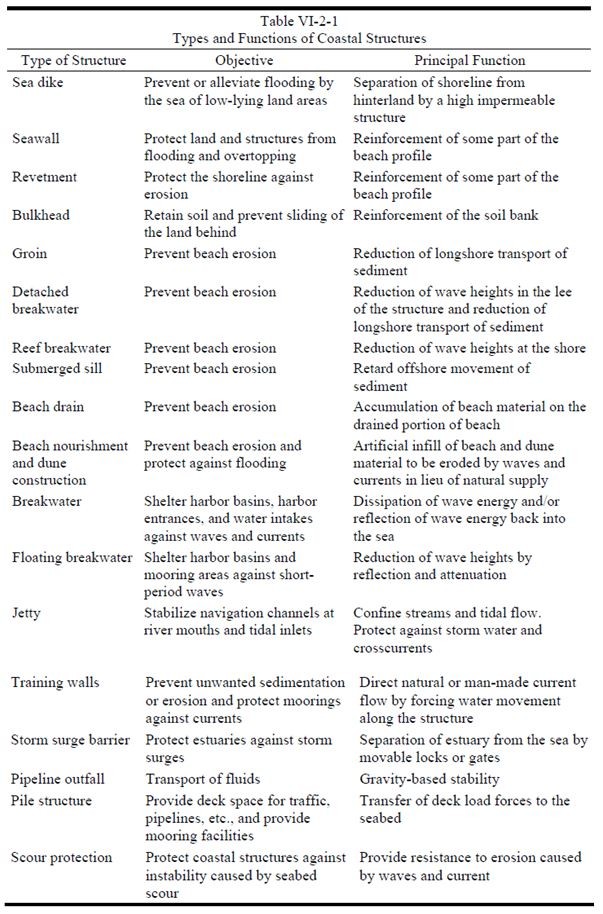
Figure 15-34. Table VI-2-1 from Coastal Engineering Manual (USACE, 2002).
Coastal Roadway Design Considerations
Roadway design in coastal environments can begin similar to upland roadway design. The roadway geometry and layout should consider, when applicable, locations that have minimal impacts from nearshore processes. The roadway elevation should consider the design elevation (Section 4) to include any additional height requirements to avoid overtopping or wave splash impacts on the pavement structure. If raising the grade is not preferred or possible, other techniques mentioned in Section 5 for overwash should be applied to protect the roadway during overwash conditions. If the roadway is adjacent or close to areas where wave action and storm surge can impact the structure, protection of the embankment should be considered.
Hard structures often considered as a complement in roadway design from Figure 15-34 above include revetments and seawalls. Revetments and seawalls start with similar design considerations, primarily wave concerns. Revetments are onshore structures with the principal function of protecting the shoreline from erosion. Revetment sizing was discussed with regards to design wave height in Section 3 and Hudson’s formula for particle sizing in Section 5. Seawalls, also discussed in Section 5, are used to protect promenades, roads, and buildings placed seaward side of the beach on the slope next to the top of the dune. The USACE
provides typical cross sections and layouts as well as example design problems for these structures, as seen in Figure 15-35 below.
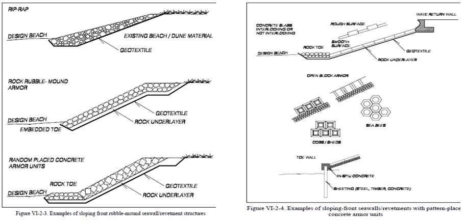
Figure 15-35. Seawall and Revetment Guidance from Coastal Engineering Manual (USACE, 2002)
Although there is always some risk associated with the design of coastal roadways, significant risks are those classified as having a probability of catastrophic failure with loss of life, or when a road is the only vehicular egress route available to a community. Roadways designated as evacuation routes or sole egress should be designed to a higher standard; for example, applying a higher freeboard than AASHTO requires would allow efficient and effective inland evacuation. For instance, it is common practice to design the roadway elevation of an evacuation corridor to be at or above a 100-year return period design elevation. Similarly, the evacuation road corridor may also be designed to survive overwashing during the storm event to minimize road damage and thus allow post-storm emergency first responders and supplies to quickly re-enter an affected area. Evacuation corridors are also commonly designed with additional capacity (including options for contraflow) to remove bottlenecks, allowing safe transportation of people and goods in times of excessive demand on the roadways (Figure 15-36).
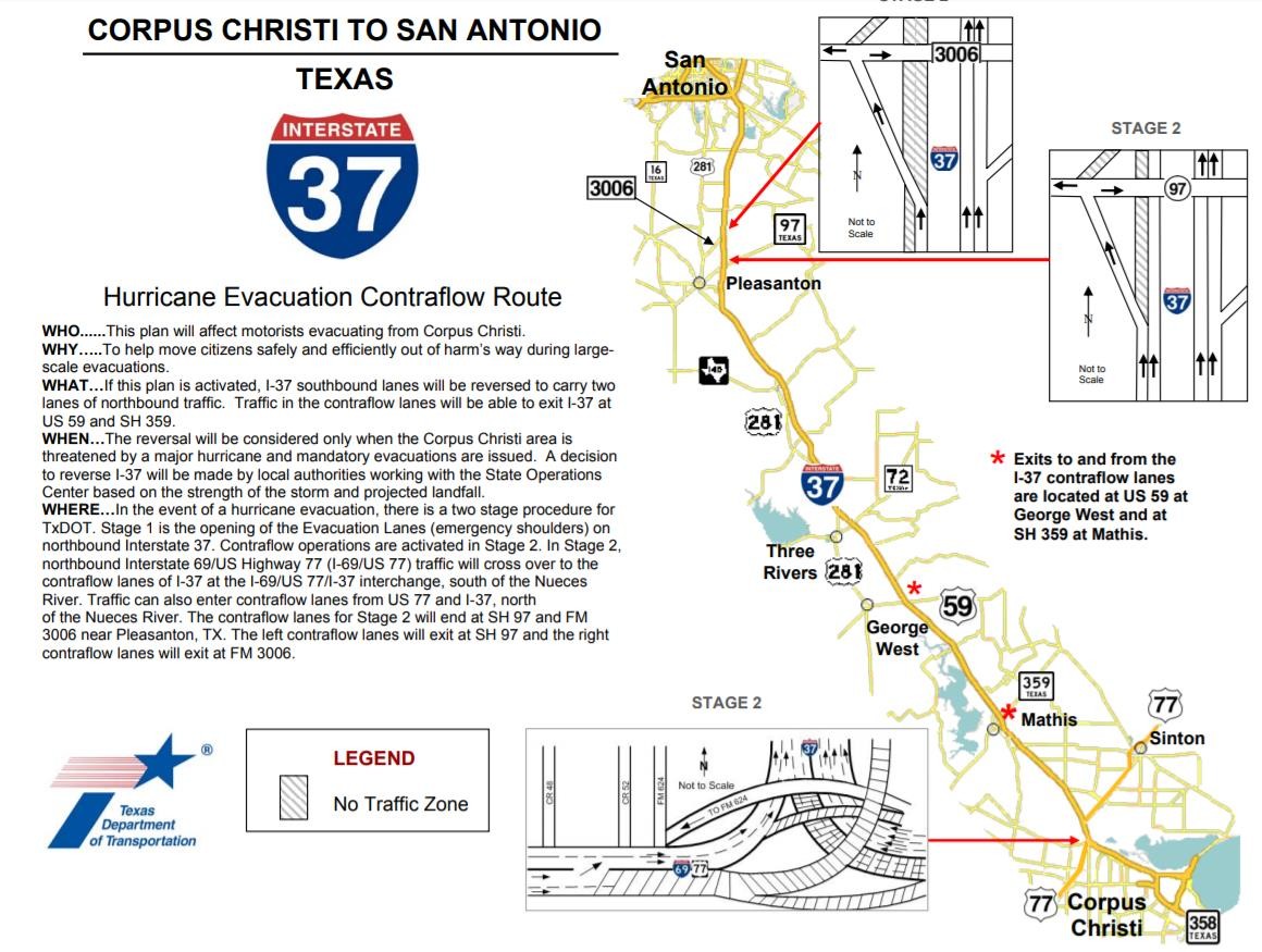
Figure 15-36. I-37 Contraflow Plan Corpus Christi.
Coastal Bridge Design Considerations
Hydraulic bridge design typically starts with an assessment of hydraulic capacity and evaluation of design elevation for the low chord. Other design considerations include bridge length, span arrangement, abutment location, and pier arrangement. The process for creating a design elevation is discussed in Section 4. Once the design elevation is determined, the proposed bridge design can be evaluated for environmental impacts, changes in nearshore processes, and can be structurally designed to withstand the various coastal loads. Hydraulic considerations vary between riverine and coastal scenarios, with many designs requiring consideration of both, or even cumulative effects, for proper assessments.
One type of hard coastal structures listed in the previous table and described in detail in the USACE CEM is pile structures. The most common pile structures in coastal engineering are bridge piers. Pile structures are designed based on the bearing capacity and settlement characteristics of the seabed. With coastal bridges, the substructure and how it interacts with the superstructure and deck can be quite complex. In addition to the bridge deck and piers carrying loads from traffic, the pile structures of the piers are exposed to loads from waves and currents that can result in scouring. Where scour analyses or geotechnical reports indicate potential instability at pile structures, scour protection can be placed. Scour protection often consists of rock bed on a stone or geotextile filter; however, specialty designed concrete block and mattress systems are also used. Scour protection was discussed in Section 5 with regards to methods to determine scour depth, along with recommended resources for determining countermeasures. In addition, as mentioned in Section 5, both FHWA
and the USACE
discuss coastal scour and scour protection.
Many variables can be important in determining forces on piles subjected to wave action. Besides scour potential, wave and current load forces on the piles should be reviewed, if applicable, for structural instability. Although the analysis can be quite complex (refer to HEC-25 and the CEM for guidance), there are some factors that can be taken in to account during design that help reduce impacts. Some factors the designer can control include: pile diameter, pile shape, pile roughness, and pile orientation to the flow field. Factors that impact pile wave forces but are not controllable by the designer include: wave height, water depth, and wave period/wavelength. Figure 15-37 below shows the wave forces on a vertical cylinder.
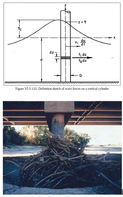
Figure 15-37. Coastal Engineering Manual Vertical Wave Forces on a Vertical Cylinder (USACE, 2002)
When possible, or when determined as part of a project scope, the site-specific wave forces on the bridge pier design should be evaluated. When this is not possible or other standards are used for pier construction, there are recommendations that can help minimize wave forces. Rounded piles have beneficial structural properties and have less resistance to flow than rectangular piles. Spacing of piles along a bent can also impact the flow field. For multiple columns skewed to the flow direction, the scour depth can be significantly affected by the spacing between the columns. When possible, rounded, well-spaced piles aligned to the flow field can reduce risk of potential scour and limit the bridge backwater.
Additional Coastal Design Considerations
Additional design considerations include geotechnical, multimodal traffic, utilities, environmental, community access, and design aesthetics.
When designing a roadway, a geotechnical investigation is required to evaluate the anticipated pavement design and to consider potential failure mechanisms from nearshore processes, like overwashing and wave action. In both bridge and roadway design, the interaction between coastal infrastructure and underlying soil is a critical aspect of project performance. In addition, a bridge scour analysis could not be conducted without this investigation since the channel bed particle size and behavior is at the core of the scour equations.
Environmental regulations and identified environmental concerns should be reviewed for the project site prior to design. Addressing environmental concerns would involve a review of potential impacts that may result in ecological changes, even those changes that may be beneficial. Permits, consultations, and/or coordination with resource and regulatory agencies may be required for potential impacts to the water itself, navigability of the waterway, state and federally protected species, archeological and historic resources, and many other environmental resources. Permits, consultations, and coordination with regulatory and resource protection agencies can require increased environmental review of anticipated impacts from a proposed design and can be expected to increase the cost and timeframe required to deliver a project. Working closely with the Environmental Affairs Division and District environmental staff to identify environmental constraints and permitting pathways early in design will ultimately benefit project delivery.
When planning for new or improved infrastructure in a coastal area, especially a bridge, the volume of traffic is often a concern. Also, a potential concern is the ability for traffic, particularly aquatic vessel traffic, to pass under the bridge with sufficient vertical clearance in areas like the Gulf Intracoastal Waterway, which are travel ways for very large barges. There may also be existing or future utilities that need to be considered in the allowable vertical clearance for roadway and bridge traffic, in bridge design loads, or in placement of piers to avoid subsurface conflicts.
When designing new or improved coastal infrastructure, the existing condition should be evaluated for community needs. For instance, if a new or improved roadway is being designed and a new revetment is needed along the seaward side, the revetment may impact recreation or community access to the shoreline. Areas around coastlines are very often used for fishing, kayaking, swimming, and other activities. An evaluation should be performed to determine if the proposed infrastructure will impact the current community use of the coastline or region.
Proposed coastal infrastructure projects could have potentially significant impacts related to effects on a scenic vista or degradation of the existing visual character of a project area. Hard coastal structures are beneficial for erosion control but can often create aesthetic or shoreline access concerns for the community. Community engagement and feedback on the proposed design should be considered to ensure infrastructure projects can meet both design criteria and local stakeholder needs.
Living Shorelines
Transportation systems within the coastal zone are subject to highly dynamic systems and are susceptible to changing water levels, storm surge, currents, and wave attack. Because these forces are often very large and varied, identifying design techniques that can mitigate and adapt to meet future risks is valuable to extending project life cycles. Living shoreline techniques involve combining ecologically-based mitigation techniques, such as coastal vegetation, with hardened solutions, such as breakwaters or revetments, to create strong, but also more adaptable systems. Living shorelines can provide long-term risk mitigation due to their more dynamic nature, as they incorporate natural processes, such as sedimentation and vegetation growth, that can rise or adapt—to some extent-- with long-term changes such as relative sea level rise.
Incorporating local natural elements, particularly vegetation, can lead to a more resilient transportation structure that includes nature-based buffers between the transportation system and the dynamic forces of coastal waters. In addition to coastal vegetation, these designs can include sediment capture or shoreline stabilization features along beaches or other shoreline systems. Such natural elements are more dynamic and adaptable to nearshore processes, which can be beneficial in adapting to changing shoreline conditions and water levels. For projects located near shorelines, it is recommended to evaluate living shoreline techniques for cost effective applicability to promote project longevity and risk mitigation over traditional hard armoring techniques. Examples of shoreline stabilization relevant to living shoreline techniques are shown in Figure 15-38 below. Marsh grasses and nearshore man-made oyster reefs submerged breakwaters, much like the example below, have been planted and constructed along Broadway Street in Little Bay, providing roadway infrastructure in Aransas County with a more resilient long-term solution to erosive coastal forces.
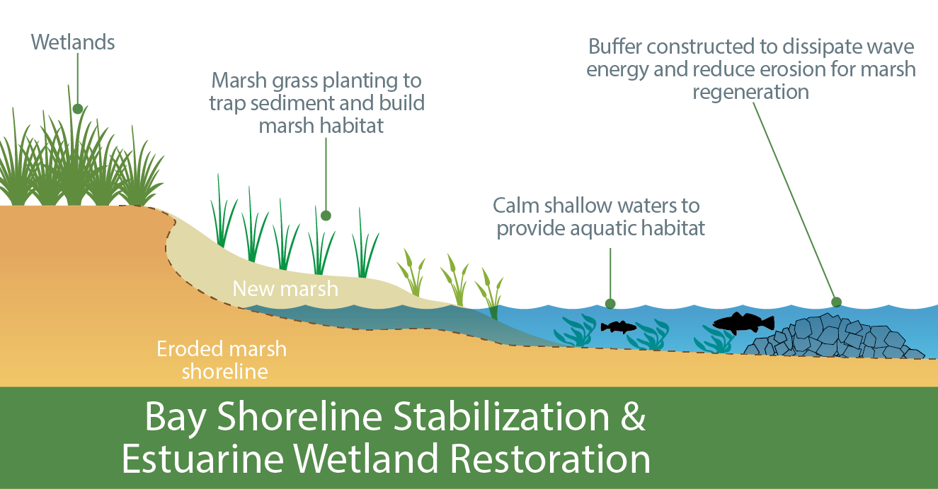
Figure 15-38. Living Shoreline Example Section.
Additional living shoreline references include
and the
.