Scour
Scour is addressed elsewhere in this Manual for cases involving hydraulics for bridges (Chapter 9), reservoirs (Chapter 12), and storm water management (Chapter 13). Scour occurring in a coastal environment is fundamentally different than riverine scour. In the coastal environment, the primary driver of scour is from head differences across a structure driven by storm tide, which are propagating inland. Riverine scour is typically opposite in direction and is driven primarily by storm runoff, resulting in different mechanisms and directions for scour considerations. Many coastal structures require analyzing for both riverine and coastal scour, and some scenarios require evaluation of combined effects.
classifies three levels of approach for coastal scour which will be discussed later. A Level 3 analysis should be evaluated by a precertified TxDOT engineer with experience in coastal processes.
This section focuses on scour due to coastal exposure including storm surge, waves, and tidal currents. Scour should be assessed or evaluated for most projects, especially in locations that may have significant water velocities at the large scale or localized levels. The potential for scour is influenced by a combination of factors including water velocity, structure configuration, bathymetry, bay/inlet configuration, sediment characteristics, and wave climate. Of particular interest for TxDOT projects is the potential for scour at bridges and roadway embankments. Scour can occur along roadway embankments from several scour mechanisms including wave action, weir-flow, and shoreline change. These mechanisms will be discussed in the next section.
All bridges need to be evaluated for scour (23 CFR 650.313(e) and FHWA, HEC-18, Evaluating Scour at Bridges). Especially susceptible locations are areas with abrupt changes in bathymetry, or tidal inlets that can cause flow constrictions or focus wave energy, and areas of active wave breaking. Other resources available to provide in-depth information, equations, and procedures to perform coastal scour include the First and Second volumes of
, Highways in the Coastal Environment, and
(Sections 9.7 and 9.8).
Scour Mechanisms
Scour results from the erosive action of flowing water, which may remove and carry away material from the bed, banks of waterway, and from around coastal structures, such as piers and abutments. Different materials scour at different rates. Loose granular soils are rapidly eroded by flowing water, while cohesive or cemented soils are generally more scour-resistant.
Determining the magnitude of scour risk at structures in coastal waters is complex, as they are at the confluence of concurrent hydraulic forces (e.g., currents and breaking waves) that arise due to the interface of the land and water. Reviewing site conditions can lead to a better anticipation of the types of scour that may be present and should be evaluated. Once the types of existing structures or planned structures are known, the list of typical scour mechanisms can be reviewed for applicability. Table 15-10 lists common scour mechanisms. Examples of many of these mechanisms are also shown in Figure 15-21.
General Scour Mechanisms | Additional Coastal Scour Mechanisms |
|---|---|
Scour around piers and abutments | Roadway damage by wave attack |
Erosion along toe of highway embankment | |
Erosion of embankment due to overtopping flow | |
Long term vertical degradation of stream bed | Roadway and railway damage by coastal “weir-flow” |
Horizontal migration of stream banks | |
Debris impact on structure | Roadway damage by bluff erosion and shoreline recession |
Clogging due to debris causing redirection of flow |
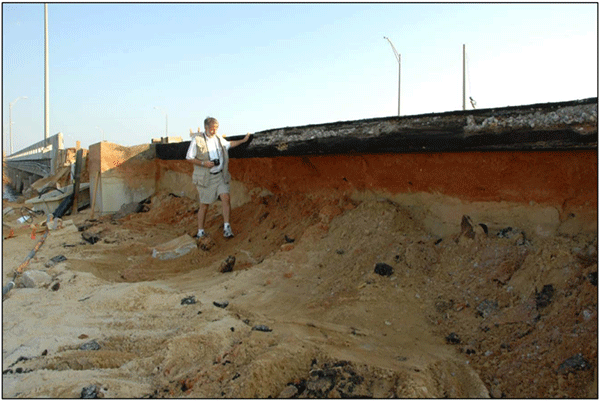 A - Partial embankment damage caused by wave attack | 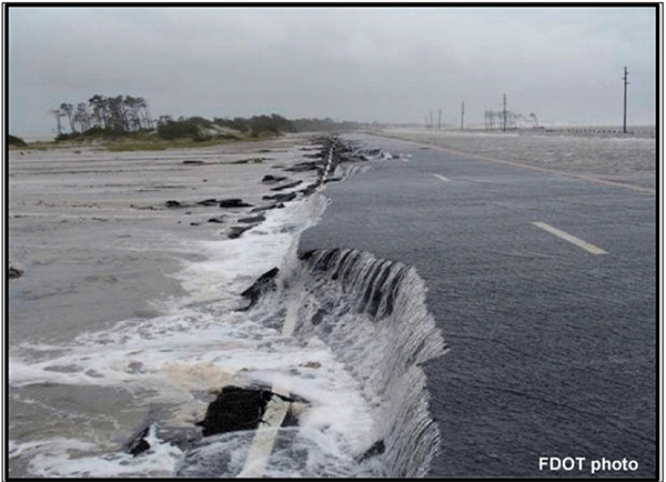 B - Example of the weir-flow damage mechanism as it occurs |
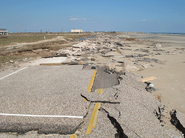 C - Pavement damage due to waves and surge in an extreme event in Brazoria County after Hurricane Ike | 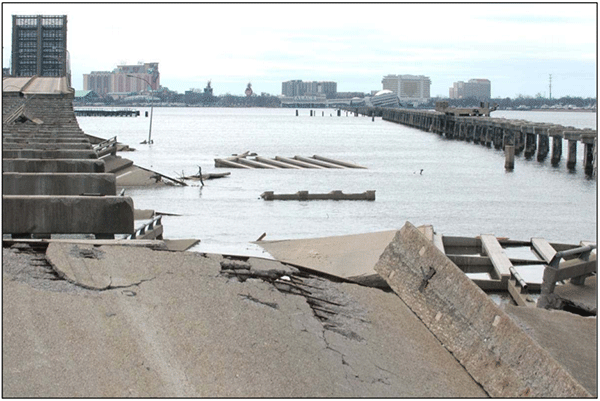 D - Two bridges destroyed by wave loads in Hurricane Katrina |
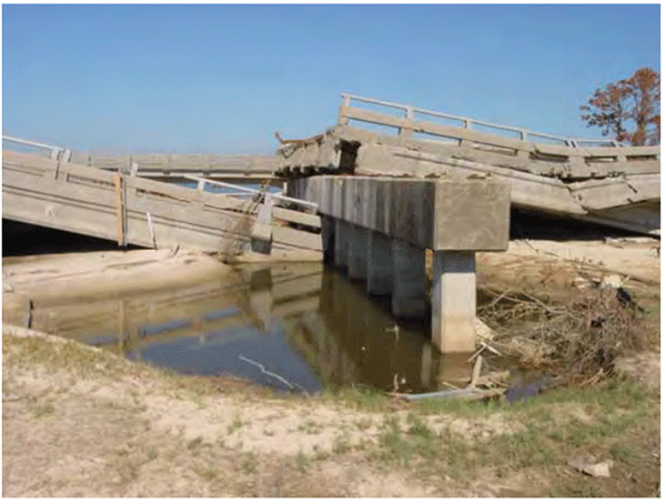 E - Wave scour hole formed by Hurricane Katrina |
Figure 15-21. Photo Examples of Coastal Scour Mechanisms (FHWA, 2008)
Hydraulic analysis must consider the magnitude of design storms, characteristics and geometry of the tidal inlet, estuary, or bay, and the long-term effects due to placement of the bridge or other transportation asset. Structures located in coastal environments must also consider scour resulting from flow in two directions due to tidal fluctuations. In addition, the analysis must consider the long-term effects of normal tidal cycles. This can be achieved by modeling and reviewing the time-dependent tidal flows, velocities, and depth on the following processes:
- Aggradation or degradation. These processes are the long-term elevation changes, which can affect the reach of the waterway on which the bridge is located. Aggradation involves the deposition of eroded material from upstream of the bridge, while degradation is the lowering of the bed of the waterway due to a deficit in sediment supply upstream.
- Contraction scour. Contraction scour is the lowering of a waterway bed at the bridge location due to constriction of the flow. This differs from degradation in that contraction scour occurs in the vicinity of the structure. Worst-case conditions of contraction scour are typically the result of storm surges.
- Local scour. Local scour involves removal of material around engineered structures caused by acceleration of flow and vortices induced by obstructions. Worst-case conditions of local scour are typically the result of storm surges.
- Channel instability. Lateral migration of the waterway occurs naturally and may affect the stability of engineered structures or change scour patterns. Channel stability is affected by local geomorphology, flood characteristics, and bed/bank materials. and FHWA’s Hydraulic Design Series Number 6 ( ) provide guidance on incorporating channel stability into roadway design.
Geotechnical investigations are commonly used to evaluate scour mechanisms. Understanding the local soil and rock properties is important, as it provides a basis for describing common engineering properties of geomaterials and how different materials may behave under various conditions. Geotechnical investigation can include surface samples, borings, and SEDflume testing. Surface samples and boring can be evaluated via Unified Soil Classification System (USCS) classifications, gradation, plasticity index, and hydrometer testing.
Due to the dynamic nature of sediment transport in the coastal zone, most technical guidance is based on empirical equations, experience, and field observations. The type of sediment located throughout the study area and suspended in the water column should be considered and equations based on available data used as appropriate. One area of focus that can vary the level of analysis needed or types of equations used is the type of soil to be evaluated, such as cohesive, non-cohesive, coarse, or erodible rock. For non-cohesive material scour equations, it is important to know the D
50
and D90
sediment diameters. For cohesive materials, when possible, it is important to know the erosion rate and critical velocity of sediment particles. These values can also be derived empirically if the D50
and classification are known.Long-term sediment budgets are also important for understanding areas prone to scouring. The long-term sediment budget can be generally characterized by typical sediment movement within the littoral zone. The littoral zone is the zone from the shoreline to just beyond the breaking wave zone. Littoral drift is the movement of beach material in the littoral zone by waves and currents. An aggrading or stable waterway may exist if the sediment supply to the project area from the littoral drift is large. Such a situation may minimize the effect of contraction scour, and possibly local scour. Conversely, long-term degradation, contraction, and local scour can be exacerbated if the sediment from littoral drift is reduced. Important information for evaluating the effect of littoral drift includes historical information, future (dredging, installation of jetties, etc.), and sources of sediment. The
Shoreline Change
subsection provides a more in-depth discussion for long-term shoreline change and sediment budgets.Once the project location is determined to be coastal (as described and shown in the maps in Section 1), the asset type to be designed or evaluated is chosen (such as a bridge), and the site’s geotechnical background is developed, then the scour mechanism(s) that apply can be evaluated. Besides the list in Table 15-10, the USACE
provides examples of locations that have a high potential for coastal scour (Figure 15-22). Other methods of determining the observed or potential scour mechanism include reviewing maintenance reports, reports from community engagement, and photos after storms.
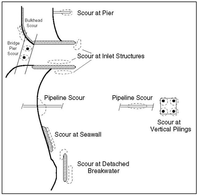
Figure 15-22. Locations with High Potential for Coastal Scour (USACE, 2002)
Understanding sediment budgets and geomorphic existing conditions provides a valuable tool for evaluating the potential for scour in tidal waterways. In most cases, this principle is not easy to quantify without direct measurements and hydraulic modeling. For the analysis of roadway structures located in tidal waterways, a three-level analysis approach, similar to the approach outlined in
, is recommended. Determining the appropriate level of analysis is dependent on-site conditions, level of approach, available data, and potential applicable scour mechanisms.
- Level 1 Analysis— Includes a qualitative evaluation of the stability of the inlet or estuary, estimating the magnitude of tides, storm conditions, flow, and long-term stability of conditions in the waterway. It is appropriate for planning phases and deliverables where uncertainty is acceptable. A Level 1 analysis is not appropriate for coastal bridge hydraulic design or scour estimates. However, a Level 1 approach can be useful in the asset management and planning phase, or when determining the potential level of effort required for a specific project.
- Level 2 Analysis— Represents the engineering assessment necessary to obtain the velocity, depths, and discharge for tidal waterways to be used in determining long-term aggradation, degradation, contraction scour, and local scour. A Level 2 analysis is suitable for a wide range of bridge sizes and types. A Level 2 analysis, when applied over the tidal prism (or volume of water contained in a tidal inlet between low and high tide levels), does include a level of uncertainty but can provide generally conservative estimates of potential scour. A Level 2 analysis is not recommended for bridges at inlets or causeway bridges.
- Level 3 Analysis— Is used for complex tidal situations that consider a larger area and a higher range of storm conditions. A Level 3 analysis can vary in complexity from one-dimensional unsteady model to advanced and physical modeling. In general, the more complex the flow parameters, the more advanced the model. provides more information regarding advanced tidal hydraulic modeling approaches.
Figure 15-23 summarizes the guidance on level of approach as it pertains to scour estimation methods.
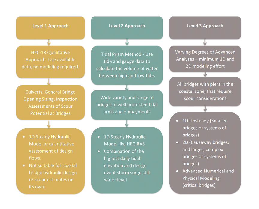
Figure 15-23. Scour Methods and Corresponding Level of Analysis.
Scour Mitigation Measures
There are several methods of infrastructure adaptation that can be incorporated during planning, designing, construction, operating, or maintaining infrastructure to mitigate for coastal scour.
recommends a five-part approach: manage and maintain, increase redundancy, protect, accommodate, and relocate. Table 15-11 summarizes each of the five steps in the recommended approach.
Manage and Maintain
| Increase Redundancy
|
Relocate
| Accommodate
|
Protection
| |
If an existing transportation asset is identified as at risk to erosion, then protection might be the first option to immediately mitigate risk. All options can be reviewed and incorporated for proposed transportation assets. For general scour conditions, such as local scour, contraction scour, stream instability, and overtopping flow, refer to Table 2.1 (Stream Instability and Bridge Scour Countermeasure Matrix) in
for guidance on reviewing the hydraulic countermeasures, structural countermeasures, biotechnical countermeasures, and monitoring as part of a scour evaluation. Since those measures are applicable for the above conditions and more well-known in riverine analysis, the remainder of this section will focus on examples of coastal protection and countermeasures.
Roadway Mitigation
Many different natural processes and forces impact roads near the coast. This section will focus on the most common erosion issues (e.g., overwashing, coastal weir-flow damage, and wave action) for roadway infrastructure.
Overwashing
:For roadways in coastal environments, highway overwashing is a very common occurrence due to nearshore locations and low elevations. There are several mechanisms that damage pavements subject to overwash including:
- Direct wave attack on the seaward shoulder of the road;
- Flow across the road and down the landward shoulder or “weir-flow”; and
- Flow parallel to the road as water moves to “breaches” or lower spots in the road as the storm surge recedes.
Coastal weir-flow and wave action will be discussed as they relate to impacts from these mechanisms later in this section.
Strategies for minimizing damage during the overwashing condition include:
- Bayside Location — Relocating the road to a portion of the barrier island where sand will likely bury the road during overwash.
- Low Elevation — Lowering the elevation of the road to be at or below much of the existing grade to encourage burial by sand during overwash. This will protect the pavement from high velocities and flows that can break-up the pavement and damage the bayside embankment.
- Dune Construction — Constructing a sand dune seaward of the road to reduce the likelihood of overwashing and to provide a reservoir of sand to bury the pavement when overwashing occurs.
- Armoring — Armoring of the shoulders of the road to resist erosion during overwashing.
Figure 15-24, below, shows the first three strategies in a roadway cross section view.
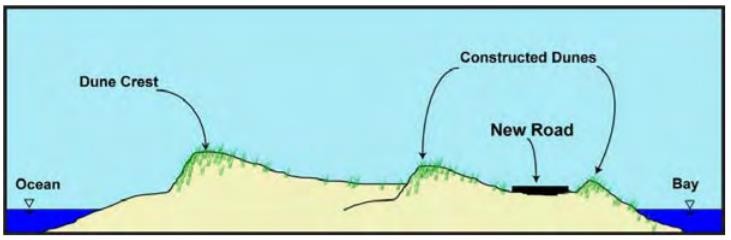
Figure 15-24. Schematic Summarizing Three Approaches (Bayside Location, Low Elevation, Dune Construction) to Minimize Damage to Roads that Overwash (FHWA, 2008)
Coastal Weir-Flow Damage:
One scour mechanism that damages pavements during overwashing is the coastal weir-flow damage mechanism. During this mechanism, water overtops the roadway embankment. The embankment acts as a broad-crested weir to the incoming storm surge. The water that flows over the embankment can become supercritical as it reaches the edge of pavement and have a free fall or a high tailwater condition. It is likely that waves will exacerbate the weir-flow damage mechanism and increase the scour risk. This happens when waves moving across the pavement with the storm surge increase the instantaneous flow velocities on the downstream shoulder. In addition to incoming storm impacts, the embankment can act as a broad-crested weir and experience similar damage mechanisms as storm surge recedes. There is also a concern of uplift on overtopped pavements due to a potential increase in underlying pore pressure in the sandy base materials.
Mitigation measures for weir-flow are similar to general overwashing. Lowering the roadway elevation to an elevation at or below adjacent ground elevations can prevent weir-flow from occurring, since the crest of the pavement is no longer the highest portion of the grade. In addition, considerations can be incorporated into the pavement design to mitigate pore pressure increases. Armoring the shoulder to withstand weir-flow mechanisms is recommended where lowering the roadway is not possible.
Wave Action:
Waves, as discussed in Section 3, cause some of the primary hydraulic forces on coastal roadway embankments. Some key variables that are often considered in revetment design to protect roadways include design wave height, potential for wave runup, and potential for overtopping splash. Where wave action and wave runup are a concern, revetment, seawalls, and bulkheads may be considered for shoreline or roadway embankment protection, as previously discussed. Relocation further inland can also reduce impacts of wave action.
Coastal Armoring for Wave Attack
Revetments, seawalls, and bulkheads are all coastal protection features designed to protect roadways and other coastal assets from dynamic coastal processes as shown in the examples in Figure 15-25. The preferred use of each option is dependent on the local conditions. Revetments are layers of protection on top of a sloped surface to protect the underlying, elevated soil. Seawalls are free-standing structures that can be stable at greater heights than revetment and are designed to protect against large wave forces. Bulkheads are designed primarily to retain the soil behind a vertical wall and are primarily used in areas with limited wave action. The fetch is a length of ocean or lake over which the wind blows in a constant direction. Given the relationship between wave height and fetch, the flowing discussion distinguishes between the three types of coastal protection and their applicability:
- Bulkheads are most common where fetches and wave heights are small, because they have limited capacity to protect against large wave forces.
- Revetments are often found in intermediate situations, such as along bays or lakes. Most transportation projects throughout Texas will rely on revetment to protect low-lying roadways, since the wave action protection provided by revetment is needed, but the height of a seawall is not required.
- Seawalls are most common where fetches and wave heights are very large, because the free-standing structures can be designed high enough to withstand larger waves and be generally more stable than revetments.
Although these three structural alternatives are the traditional approaches to coastal armoring, combinations of them with softer methods, as later discussed, are becoming more viable and can often provide more dynamic long-term protection. It is important to note that the more robust the structural alternative, such as a seawall, the more likely for residual shoreline or structural erosion adjacent to the project site. Residual impacts should be considered when evaluating project solutions.
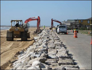 A - Revetment construction along CR257 in Brazoria County, Texas (Apollo Environmental) | 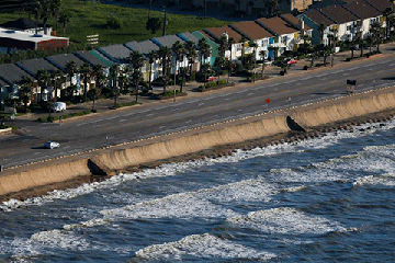 B - Galveston Seawall (Houston Chronicle) |
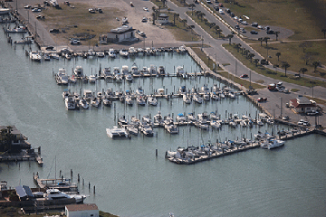 C - Bulkheads protecting roadways in Aransas County, Texas | 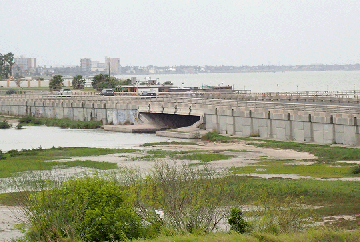 D - Vertical walls provide roadway protection along this Ocean Drive crossing in Corpus Christi, Texas |
Figure 15-25. Examples of Shoreline Protection.
A well-designed and constructed revetment can protect roadway embankments from waves. The rubble is efficient at absorbing wave energy and any damage that the revetment receives is often inexpensive to repair.
and
provide detailed procedures for the design of stone revetments and recommend Hudson’s equation to estimate stone size for the outer layer of rock revetments subject to wave action. Hudson’s equation accounts for the most important variables, including design wave height, structure slopes, and different stone densities and angularities. HEC-25 provides a more detailed description of calculations for the design wave heights for revetment design. HEC-25 also provides examples for the applicability of design alternatives depending on specific project site conditions and requirements.
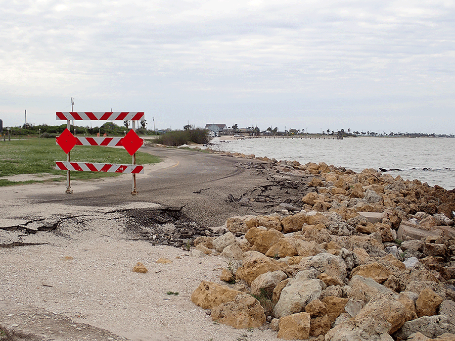
Some revetment design failure mechanisms include: inadequate armor layer design for wave action, inadequate under layer, flanking, toe scour, and overtopping splash (Figure 15-26).
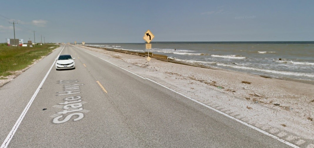 A - Toe Scour causing concrete median barriers to topple along the shoreline adjacent to SH87 near High Island, Texas |
 B - Inadequate Armor Layer - A revetment with rocks too small to withstand wave attack along SH316 in Calhoun County, Texas |
Figure 15-26. Examples of Failed Shoreline Protection.
To prevent failure mechanisms, precaution should be taken when applying design equations, like from HEC-23 or HEC-25, to ensure values used represent the intent of the equations. Stone should be sized to ensure wave action is appropriately addressed. Toe design should have significant depth of stones to prevent undermining. The protection should tie back into natural structures or adjacent resistant structures to prevent flanking and should extend high enough to prevent overtopping splash damage. The biggest risk is exposure of the underlying soil. Concrete block and panel revetment have not had a good performance record in severe coastal environments; neither approach matches the performance and flexibility of stone revetment (FHWA, 2008).
New technologies are emerging for scour protection; some examples include scour control mats and geo-fabric stone bags. As case studies develop and results are reviewed, these technologies might serve as an additional option for shoreline and structure protection (Figure 15-27).
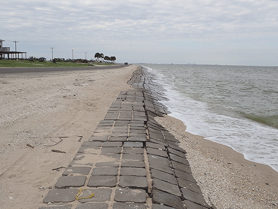
Figure 15-27. Cellular Concrete Mattresses Protecting a Coastal Highway in Calhoun County, Texas.
Other hard coastal structures that are successful in shoreline protection include groins, breakwaters, and hybrid structures (Figure 15-28). Groins are narrow, roughly shore-normal structures built to reduce longshore currents, and/or to trap and retain littoral material. Breakwaters are structures protecting a shore area, harbor, anchorage, or basin from waves. Hybrid structures are some functional combination of groins, breakwaters, or structural measures functioning in a complementary fashion. Further studies need to be conducted on all coastal protection measures, but redundancy in protection methods should be considered for adaptive designs in coastal environments.
Living shorelines, discussed more in Section 6, are techniques that involve combining ecologically-based, “soft” mitigation techniques, such as coastal vegetation, with hardened solutions, such as breakwaters. This is also a more adaptable system that can potentially provide improved long-term mitigation due to its more dynamic response to future coastal change (e.g., vegetated features can migrate with sea level rise). One example of a soft coastal protection method along roadways is beach nourishment, particularly on Gulf shorelines. Placing sand to widen a beach along with hard coastal structures can lead to a great balance between structural needs and environmental conditions to mitigate erosion.
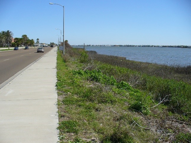 A - Wetlands and submerged oyster reef barriers provide living shoreline protection for Broadway Street in Aransas County, Texas |
 B - Groin fields shelter local roadways in Calhoun County, Texas |
Figure 15-28. Examples of Alternative Shoreline Protection Strategies.
Coastal Bridge Scour Mitigation
Engineering coastal bridges can be complex and requires consideration of forces and processes unique to the coastal environment, including tidal bridge scour and hydrodynamic loads from waves and tidal currents. The types of scour that occur at bridges in the coastal environment include the same general categories as found at riverine bridges. However, in the case of coastal bridges, scour can potentially be caused by more varied directions and magnitudes, thus increasing the complexity of analysis. Additionally, coastal bridges can experience scour as a result of wave action (wave scour) and localized areas of high velocity flows.
Methods of design equations to consider in coastal scour evaluation can be found in
,
,
, and the USACE
. Scour as defined for coastal bridges is broken into three approaches per HEC-25. For a level 3 approach as shown previously in Figure 15-23 where advanced modeling is needed because of the variety of nearshore processes, a precertified TxDOT coastal engineer should be involved. Each design storm or nearshore process scenario that is simulated should be considered for impacts on scour. Combinations of different physical processes that could increase the scour rate should be considered. For instance, if a bridge experiences tidal, wave, and storm surge conditions as part of the design storm scenarios, the hydrodynamic impacts of each condition above should be reviewed for variables like water elevation, velocity, depth, and other factors needed in scour evaluations.
Guidance documents for countermeasures included in
apply for coastal areas as they do for riverine, and include:
Design Guideline 11 - Rock Riprap at Bridge Piers
and Design Guideline 17 - Riprap Design for Wave Attack
. In Texas, riprap often refers to concrete; in FHWA guidance, riprap is typically equivalent to stone revetment. For the purpose of this chapter, riprap directly referencing a design guideline title means stone revetment.Stone revetment is a common revetment countermeasure at bridge piers and abutments. Stone revetment should follow HEC-23
Design Guideline 4 - Riprap Revetment
for guidance on sizing, gradation, placement methods, and failure mechanisms. Some failure mechanisms of stone revetment include: particle size being too small, channel changes like migration or channelization, improper gradation, improper placement, and lack of or inadequate filter. To avoid the failure mechanisms, attempts should be made to evaluate variables used for appropriateness when applying equations to size stone revetment, and any channel changes as evaluated per HEC-20 should be considered in the application for the design life of the bridge. Similar to riverine applications, HEC-23 for countermeasure design can be utilized for coastal applications methods, but all available coastal inputs should be considered and applied in the design (such as tides, wave, and storm surge).Scour Data Sources
- Federal Highway Administration
- HEC-18 – Evaluating Scour at Bridges— Chapter 9 of provides information on scour as a result of tidal currents and potential related considerations. The document outlines three levels of analysis ranging from a Level 1 qualitative analysis to a Level 3 quantitative analysis including physical models or sophisticated numerical models.
- HEC-20 – Stream Stability at Highway Structures— Chapter 2 of discusses geomorphic factors and principles, and while geared toward riverine environments, the same considerations should be applied to evaluate coastal or lake shoreline stability. Chapter 4 discusses analysis procedures for stream instability, including a discussion on mathematical and physical model studies. This would be used during a scour evaluation required by 23 CFR 650.313(e) to evaluate stream stability. Chapter 5 discusses stream reconnaissance techniques which can apply to coastal conditions in the method of data collection and conducting a field visit.
- HEC-23 – Bridge Scour and Stream Instability Countermeasures Experience, Selection, and Design Guidance—Design Guideline 17in provides guidance for stone revetment design for sites subject to wave action. Other Design Guidelines within HEC-23, can also be useful in coastal applications.
- HEC-25 – Highways in the Coastal Environment— discusses scour at coastal bridges and provides descriptions of the multiple ways that a bridge can experience scour due to different geometries. Also discussed are the time-dependent nature of scour and the influence of longer storm events.
- USACE Coastal Engineering Manual— The “Scour and Scour Protection” chapter of the provides background on the dynamic nature of coastal scour and presents several empirical methods to estimate potential scour. The chapter also discusses common structures and geometries that may induce scour.
- TxDOT Geotechnical Manual— Chapter 5 (Foundation Design), Section 6 (Scour) of thenotes that the guidelines outlined in should be used. Section 6 (Scour) also provides minimum design flood frequencies to be used for scour design. Although guidance was not separately developed for coastal settings, the same theory may be applied once controlling conditions are determined. The primary difference in using these equations for coastal settings is the need to better define input velocities and wave conditions based on the two- and three-dimensional nature of coastal hydrodynamics (for example, tides cause ebb and flood flow in tidal channels, whereas riverine flow is almost always downstream).