Section 8: Conduit Systems Energy Losses
Energy grade line (EGL) computations begin at the outfall and are worked upstream, taking each junction into consideration. Many storm drain systems are designed to function in subcritical flow. In subcritical flow, pipe and access hole losses are summed to determine the upstream EGL. In supercritical flow, pipe and access losses are not carried upstream.
Minor Energy Loss Attributions
Minor losses in a storm drain system are usually insignificant when considered individually. In a large system, however, the combined effects may be significant. The hydraulic loss potential of storm drain system features, such as junctions, bends, manholes, and confluences, can be minimized by careful design. For example, severe bends can be replaced by gradual bends where right-of-way is sufficient and increased costs are manageable. Well designed manholes and inlets without sharp or sudden transitions or impediments to the flow cause no significant losses.
Junction Loss Equation
A pipe junction is the connection of a lateral pipe to a larger trunk pipe without the use of an access hole. The minor loss equation for a pipe junction is in the form of the momentum equation. In Equation 10-36, the subscripts “i”, “o”, and “1” indicate the inlet, outlet, and lateral, respectively.
Equation 10-36.
where:
- hj= junction head loss (ft. or m)
- Q = flow (cfs or m3/s)
- v = velocity (fps or m/s)
- A = cross-sectional area (sq. ft. or m2)
- θ = angle in degrees of lateral with respect to centerline of outlet pipe
- g = gravitational acceleration = 32.2 ft/s2or 9.81 m/s2.
The above equation applies only if v
o
> vi
and assumes that Qo
= Qi
+ Q1
.Exit Loss Equation
The exit loss, h
o
, is a function of the change in velocity at the outlet of the pipe as shown in Equation 10-37.
Equation 10-37.
where:
- v = average outlet velocity (fps or m/s)
- vd= channel velocity downstream of the outlet (fps or m/s)
- Co= exit loss coefficient (0.5 typical).
The above assumes that the channel velocity is lower than the outlet velocity. Note that, for partial flow, where the pipe outfalls into a channel with water moving in the same direction, the exit loss may be reduced to virtually zero.
Inlet and Access Hole Energy Loss Equations
, Chapter 7 presents a new method to compute energy losses for inlets and access holes.
As a starting point, the outflow pipe energy head (E
i
) is the difference between the energy gradeline in the outflow pipe (EGLi
) and the outflow pipe flowline, as shown on Figure 10-20.
Equation 10-38.
where:
- Ei= Outflow pipe energy head (ft. or m)
- EGLi= Outflow pipe energy gradeline
- Zi= Outflow pipe flowline elevation
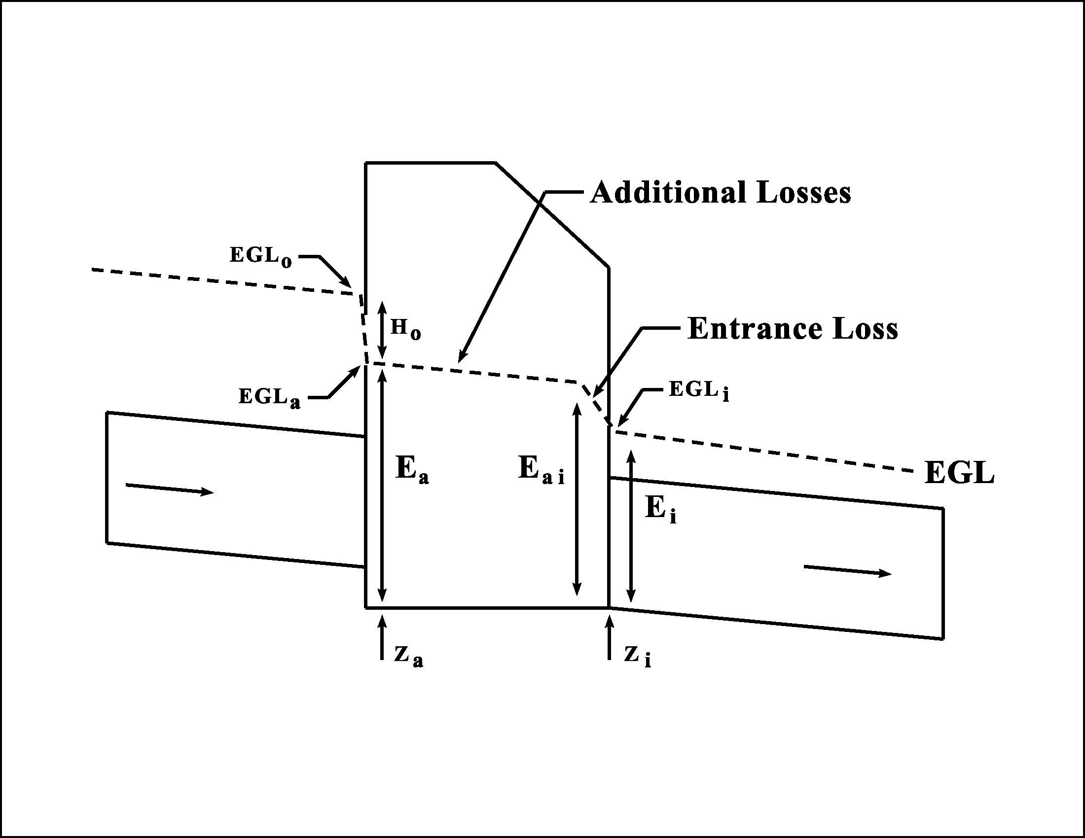
Figure 10-23. Access Hole Energy Level Definitions
Initial Access Hole Energy Level
The initial estimate of energy level (E
ai
) is taken as the maximum of the three values, Eaio
, Eais
, and Eaiu
:
Equation 10-39.
where:
- Eaio= Estimated access hole energy level for outlet control (full and partial flow)
- Eais= Estimated access hole energy level for inlet control (submerged)
- Eaiu= Estimated access hole energy level for inlet control (unsubmerged)
E
aio
-- Estimated Energy Level for Outlet Control
In the outlet control condition, flow out of the access hole is limited by the downstream storm drain system. The outflow pipe would be in subcritical flow and could be either flowing full or partially full.
Whether the outflow pipe is flowing full or partially full affects the value of E
aio
. This can be determined by redescribing and rearranging the outflow pipe energy head, Ei
. Ei
can be described as the sum of the potential head, pressure head, and velocity head, as shown in Equation 10-40.
Equation 10-40.
where:
Rearranging Equation 40 to isolate the potential head and pressure head gives Equation 41:
- γ = Outflow pipe depth (potential head) (ft. or m)
- (P / γ) = Outflow pipe pressure head (ft. or m)
- (v2/2g) = Outflow pipe velocity head (ft. or m).
Equation 10-41.
If y + (P / γ) is less than the diameter of the outflow pipe, then the pipe is in partial flow and the estimated initial structure energy level (E
aio
) is equal to zero (Eaio
= 0).If y + (P / γ) is greater than the diameter of the outflow pipe, then the pipe is in full flow, and the estimated initial structure energy level (E
aio
) is calculated using Equation 10-42:
Equation 10-42.
where:
- Ei= Outflow pipe energy head (ft. or m)
- Hi= entrance loss assuming outlet control, using Equation 10-43
Equation 10-43.
where:
- V2/2g = Outflow pipe velocity head (ft. or m)Eais-- Estimated Energy Level for Inlet Control: SubmergedThe submerged inlet control energy level (Eais) checks the orifice condition and is estimated using Equation 10-44:
Equation 10-44.
where:
- DI is the Discharge Intensity parameter, calculated by Equation 10-45:
Equation 10-45.
where:
- DI = Discharge Intensity parameter
- Q = flow in outfall pipe (cfs or m3/s)
- A = Area of outflow pipe (ft2or m2)
- Do= Diameter of outflow pipe (ft. or m)Eaiu-- Estimated Energy Level for Inlet Control: UnsubmergedThe unsubmerged inlet control energy level (Eaiu) checks the weir condition and is estimated using Equation 10-46:
Equation 10-46.
Adjustments for Benching, Angled Inflow, and Plunging Inflow
The revised access hole energy level (E
a
) is determined by adding three loss factors for: (1) benching configurations; (2) flows entering the structure at an angle; and (3) plunging flows. Flows entering a structure from an inlet can be treated as plunging flows.
Equation 10-47.
where:
- Ea= the revised access hole energy level
- Eai= the initial estimate of access hole energy level, calculated using Equation 10-39
- Ha= additional energy loss due to benching, angled inflow and plunging inflow, calculated using Equation 10-48.
If E
a
is calculated to be less than the outflow pipe energy head (Ei
), then Ea
should be set equal to Ei
.
Equation 10-48.
where:
- CB= Coefficient for benching (floor configuration)
- Cθ= Coefficient for angled flows
- CP= Coefficient for plunging flows
Note that the value of H
a
should always be positive. If not, Ha
should be set to zero.Additional Energy Loss: Benching
Benching serves to direct flow through the access hole, which reduces energy losses. Figure 10-21 illustrates some typical bench configurations. Department standard sheets do not show any benching practices other than methods (a) and (b).
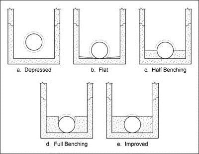
Figure 10-24. Access hole benching methods
The energy loss coefficient for benching, (C
B
), is obtained from Table 10-4. A negative value indicates water depth will be decreased rather than increased.Floor Configuration | C B |
Flat (level) | -0.05 |
Depressed | 0.0 |
Unknown | -0.05 |
Additional Energy Loss: Angled Inflow
The angles of all inflow pipes into the access hole are combined into a single weighted angle (θ
w
) using Equation 10-49:
Equation 10-49.
where:
- QJ= Contributing flow from inflow pipe, cfs
- θJ= Angle measured from the outlet pipe (degrees)(plunging flow is 180 degrees)
Figure 10-22 illustrates the orientation of the pipe inflow angle measurement. The angle for each inflow pipe is referenced to the outlet pipe, so that the angle is not greater than 180 degrees. A straight pipe angle is 180 degrees. If all flows are plunging, θ
w
is set to 180 degrees; the angled inflow coefficient approaches zero as θw
approaches 180 degrees and the relative inflow approaches zero. The angled inflow coefficient (Cθ
) is calculated by Equation 10-50:
Equation 10-50.
where:
Q
o
= Flow in outflow pipe, cfs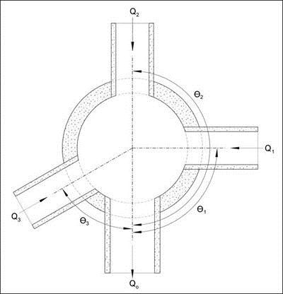
Figure 10-25. Access hole angled inflow definition.
Additional Energy Loss: Plunging Inflow
Plunging inflow is defined as inflow from an inlet or a pipe where the pipe flowline is above the estimated access hole water depth (approximated by E
ai
).The relative plunge height (h
k
) for each inflow pipe is calculated using Equation 10-51:
Equation 10-51.
where:
- Zk= the difference between the inflow pipe flowline elevation and the access hole flowline elevation. If Zk> 10Doit should be set to 10Do.
The relative plunge height for each inflow pipe is calculated separately and then combined into a single plunging flow coefficient (C
P
):
Equation 10-52.
As the proportion of plunging flows approaches zero, C
P
also approaches zero.Access Hole Energy Gradeline
Knowing the access hole energy level (E
a
) and assuming that the access hole flowline (Za
) is the same elevation as the outflow pipe flowline (Zi
) allows determination of the access hole energy gradeline (EGLa
):
Equation 10-53.
As described earlier, the potentially highly turbulent nature of flow within the access hole makes determination of water depth problematic. Research has shown that determining velocity head within the access hole is very difficult, even in controlled laboratory conditions. However, a reasonable assumption is to use the EGL
a
as a comparison elevation to check for potential surcharging of the system.Inflow Pipe Exit Losses
The final step is to calculate the energy gradeline into each inflow pipe, whether plunging or non-plunging.
Non-Plunging Inflow Pipe
Non-plunging inflow pipes are those pipes with a hydraulic connection to the water in the access hole. Inflow pipes operating under this condition are identified when the revised access hole energy gradeline (E
a
) is greater than the inflow pipe flowline elevation (Zo
). In this case, the inflow pipe energy head (EGLo
) is equal to:
Equation 10-54.
where:
H
o
= 0.4(V2
/2g) = Inflow pipe exit lossExit loss is calculated in the traditional manner using the inflow pipe velocity head since a condition of supercritical flow is not a concern on the inflow pipe.
Plunging Inflow Pipe
For plunging inflow pipes, the inflow pipe energy gradeline (EGL
o
) is logically independent of access hole water depth and losses. Determining the energy gradeline for the outlet of a pipe has already been described in
.Continuing Computations Upstream
For either the nonplunging or plunging flows, the resulting energy gradeline is used to continue computations upstream to the next access hole. The procedure of estimating entrance losses, additional losses, and exit losses is repeated at each access hole.
Energy Gradeline Procedure
- Determine the EGLiand HGLidownstream of the access hole. The EGL and HGL will most likely need to be followed all the way from the outfall. If the system is being connected to an existing storm drain, the EGL and HGL will be that of the existing storm drain.
- Verify flow conditions at the outflow pipe.
- If HGLiis greater or equal to the soffit of the outflow pipe, the pipe is in full flow.
- If HGLiis less than the soffit of the outflow pipe but greater than critical depth, the pipe is not in full flow but downstream conditions still control.
- If HGLiis less than the soffit of the outflow pipe but greater than critical depth and less than or equal to normal depth, the pipe is in subcritical partial flow. EGLibecomes the flowline elevation plus normal depth plus the velocity head.
- If HGLiis less than critical depth, the pipe is in supercritical partial flow conditions. Pipe losses in a supercritical pipe section are not carried upstream.
- Estimate Ei(outflow pipe energy head) by subtracting Zi(pipe flowline elevation) from the EGLiusing Equation 10-38. Calculateγ+ P/γusing Equation 10-41. Compute DI using Equation 10-45.
- Calculate Eaias maximum of Eaio, Eais, and Eaiuas below:
- If (γ+ P/γ)>D, then the pipe is in full flow and Eaio= Ei+ Hi(Equation 10-42). If (γ+ P/γ) < D, then the pipe is in partial flow and Eaio= 0.
- Eais= Do(DI)2(Equation 10-44)
- Eaiu= 1.6 Do(DI)0.67(Equation 10-46)
If Eai< Ei, the head loss through the access hole will be zero, and Eai= Ei. Go to Step 10. - Determine the benching coefficient (CB) using Table 10-4. Department standard sheets do not show any benching practices other than depressed (a) or flat (b). The values are the same whether the bench is submerged or unsubmerged.
- Determine the energy loss coefficient for angle flow (Cθ) by determining θWfor every pipe into the access hole.
- Is Ei< inflow pipe flowline? If so, then the flow is plunging and θWfor that pipe is 180 degrees.
- If the pipe angle is straight, then θWfor that pipe is 180 degrees.
- Otherwise, θWis the angle of the inflow pipe relevant to the outflow pipe. Maximum angle is 180 degrees (straight).
Use Equation 10-49 and Equation 10-50 to calculate θWand Cθ. - Determine the plunging flow coefficient (CP) for every pipe into the access hole using Equation 10-52. The relative plunge height (hk) is calculated using Equation 10-51. Zkis the difference between the access hole flowline elevation and the inflow pipe flowline elevation. If Zk> 10Do, Zkshould be set to 10Do.
- If the initial estimate of the access hole energy level is greater than the outflow pipe energy head (Eai> Ei), then Ea= Ei. If Eai≤ Ei, then Ha= (Eai- Ei)(CB+ Cθ+ CP). If Ha< 0, set Ha= 0.
- Calculate the revised access hole energy level (Ea) using Equation 10-47. If Ea< Ei, set Ea= Ei.
- Compute EGLaby adding Eato the outflow pipe flowline elevation. Assume HGLaat the access hole structure is equal to EGLa.
- Compare EGLawith the critical elevation (ground surface, top of grate, gutter elevation, or other limits). If EGLaexceeds the critical elevation, modifications must be made to the design.