Design Procedure for Grate Inlets in Sag Configurations
A grate inlet in sag configuration operates in weir flow at low ponded depths but transitions to orifice flow as the ponded depth increases. The following procedure is used for calculating the inlet capacity:
- Choose a grate of standard dimensions to use as a basis for calculations.
- Determine an allowable head (h) for the inlet location. For a grate in a curb and gutter section, this should be the lower of the curb height or the depth associated with the allowable ponded width. For a grate in a ditch (drop inlet), this should be the lower of the height of the ditch block, if any, or the allowable ponded depth. No gutter depression is applied at grate inlets.
- Determine the capacity of a grate inlet operating as a weir. Under weir conditions, the grate perimeter controls the capacity. Figure 10-16 shows the perimeter length for a grate inlet located next to and away from a curb. The capacity of a grate inlet operating as a weir is determined using Equation 10-30.
 Equation 10-30.where:
- QW= weir capacity of grate (cfs or m3/s)
- CW= weir coefficient = 3 for English measurement or 1.66 for metric
- P = perimeter of the grate (ft. or m) as shown in Figure 10-16: A multiplier of about 0.5 is recommended to be applied to the measured perimeter as a safety factor.
- h = allowable head on grate (ft. or m).
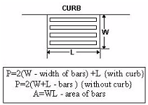 Figure 10-19. Perimeter Length for Grate Inlet in Sag Configuration
 - Determine the capacity of a grate inlet operating under orifice flow. Under orifice conditions, the grate area controls the capacity. The capacity of a grate inlet operating under orifice flow is computed with Equation 10-31.Equation 10-31.
 where:
- Qo= orifice capacity of grate (cfs or m3/s)
- Co= orifice flow coefficient = 0.67
- A = clear opening area (sq. ft. or m2) of the grate (the total area available for flow). A multiplier of about 0.5 is recommended to be applied to the measured area as a safety factor
- g = acceleration due to gravity (32.2 ft/s2or 9.81 m/s2)
- h = allowable head on grate (ft. or m).
- Compare the calculated capacities from steps 3 and 4 and choose the lower value as the design capacity. The design capacity of a grated inlet in sag is based on the minimum flow calculated from weir and orifice conditions. Figure 10-17 demonstrates the relationship between weir and orifice flow. If Qois greater than Qw(to the left of the intersection in Figure 10-17), then the designer would use the capacity calculated with the weir equation. If, however, Qois less than Qw(to the right of the intersection), then the capacity as determined with the orifice equation would be used.
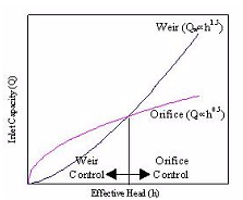 Figure 10-20. Relationship between Head and Capacity for Weir and Orifice Flow