Curb Inlets On-Grade
The design of on-grade curb opening inlets involves determination of length required for total flow interception, subjective decision about actual length to be provided, and determination of any resulting carryover rate.
The following procedure is used to design curb inlets on-grade:
- Compute depth of flow and ponded width (T) in the gutter section at the inlet.
- Determine the ratio of the width of flow in the depressed section (W) to the width of total gutter flow (T) using Equation 10-5. Figure 10-14 shows the gutter cross section at an inlet.
 Equation 10-5.where:
- E0= ratio of depression flow to total flow
- KW= conveyance of the depressed gutter section (cfs or m3/s)
- K0= conveyance of the gutter section beyond the depression (cfs or m3/s).
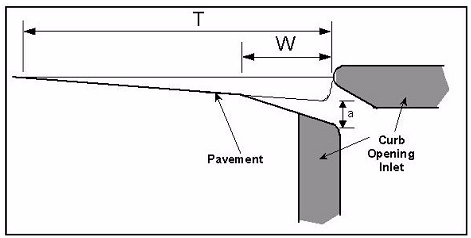 Figure 10-17. Gutter Cross-Section DiagramUse Equation 10-6 to calculate conveyance, KWand K0.
 Equation 10-6.where:
- K = conveyance of cross section (cfs or m3/s)
- z = 1.486 for English measurements and 1.0 for metric
- A = area of cross section (sq.ft. or m2)
- n = Manning’s roughness coefficient
- P = wetted perimeter (ft. or m).
Use Equation 10-7 to calculate the area of cross section in the depressed gutter section. Equation 10-7.where:
- AW= area of depressed gutter section (ft2or m2)
- W = depression width for an on-grade curb inlet (ft. or m)
- Sx= cross slope (ft./ft. or m/m)
- T = calculated ponded width (ft. or m)
- a = curb opening depression depth (ft. or m).
Use Equation 10-8 to calculate the wetted perimeter in the depressed gutter section. Equation 10-8.where:
- PW= wetted perimeter of depressed gutter section (ft. or m)
- W = depression width for an on-grade curb inlet (ft. or m)
- Sx= cross slope (ft./ft. or m/m)
- a = curb opening depression depth (ft. or m).
Use Equation 10-9 to calculate the area of cross section of the gutter section beyond the depression. Equation 10-9.where:
- A0= area of gutter/road section beyond the depression width (ft2or m2)
- Sx= cross slope (ft./ft. or m/m)
- W = depression width for an on-grade curb inlet (ft. or m)
- T = calculated ponded width
Use Equation 10-10 to calculate the wetted perimeter of the gutter section beyond the depression. Equation 10-10.where:
- P0= wetted perimeter of the depressed gutter section (ft. or m)
- T = calculated ponded width (ft. or m)
- W = depression width for an on-grade curb inlet (ft. or m).
- Use Equation 10-11 to determine the equivalent cross slope (Se) for a depressed curb opening inlet.
 Equation 10-11.where:
- Se= equivalent cross slope (ft./ft. or m/m)
- Sx= cross slope of the road (ft./ft. or m/m)
- a = gutter depression depth (ft. or m)
- W = gutter depression width (ft. or m)
- Eo= ratio of depression flow to total flow.
- Calculate the length of curb inlet required for total interception using Equation 10-12.
 Equation 10-12.where:
- Lr= length of curb inlet required (ft. or m)
- z = 0.6 for English measurement and 0.82 for metric
- Q = flow rate in gutter (cfs or m3/s)
- S = longitudinal slope (ft./ft. or m/m)
- n = Manning’s roughness coefficient
- Se= equivalent cross slope (ft./ft. or m/m).
If no bypass flow is allowed, the inlet length is assigned a nominal dimension of at least Lr, which should be an available (nominal) standard curb opening length. The exact value of Lrshould not be used if doing so requires special details, special drawings, structural design, and costly construction.If bypass flow is allowed, the inlet length is rounded down to the next available standard (nominal) curb opening length. - Determine bypass flow. In bypass flow computations, efficiency of flow interception varies with the ratio of actual length of curb opening inlet supplied (La) to required length (Lr) and with the depression to depth of flow ratio. Use Equation 10-13 to calculate bypass flow.
 Equation 10-13.where:
- Qco= carryover discharge (cfs or m3/s)
- Q = total discharge (cfs or m3/s)
- La= design length of the curb opening inlet (ft. or m)
- Lr= length of curb opening inlet required to intercept the total flow (ft. or m).
Bypass flows usually should not exceed about 0.5 cfs (0.03 m3/s). Greater rates can be troublesome and cause a significant departure from the principles of the Rational Method application. In all cases, the bypass flow must be accommodated at some other specified point in the storm drain system. - Calculate the intercepted flow as the original discharge in the approach curb and gutter minus the amount of bypass flow.