Frontage Roads
Frontage roads are roadways that are constructed generally parallel to a freeway or other highway. Figure 2-2 shows a typical frontage road application. Freeway frontage roads normally have at-grade interchanges with the arterial streets, which are generally perpendicular to the freeway and are grade-separated from the freeway mainlanes. Under fully developed conditions, the at-grade intersections of frontage roads and arterials are typically signalized.
Ramps provide connections between the frontage roads and the freeway. Traffic traveling from an arterial street to the freeway first turns from the arterial onto the frontage road and then travels along the frontage road to a freeway entrance ramp. Traffic traveling from the freeway to an arterial street leaves the freeway by means of an exit ramp that connects to the frontage road and then travels along the frontage road to its intersection with the arterial street.
Direct access to the frontage road is prohibited in the vicinity of ramp connections, as described in the TxDOT
Roadway Design Manual
, Chapter 3.Other streets may also intersect with frontage roads. By means of these intersections, access is provided between the freeway system and the developments that have access onto these streets.
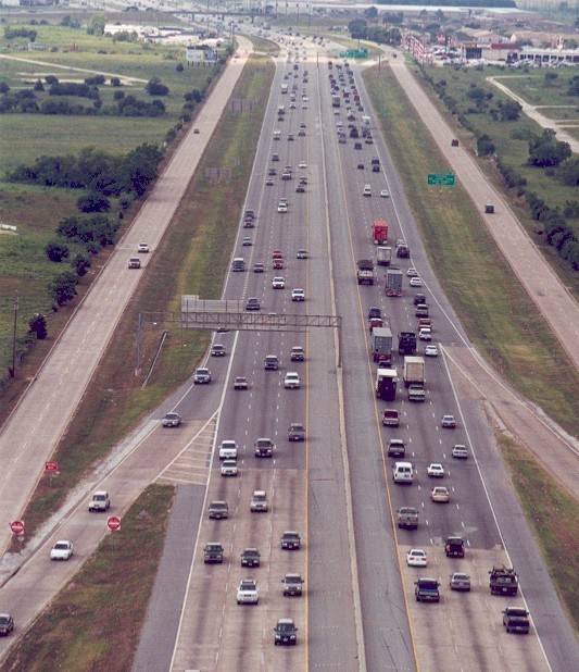
Figure 2-2. Freeway with Frontage Roads
Frontage roads may be considered in order to provide direct access to abutting property where 1) alternative access is not available and the property would otherwise be landlocked, 2) it is not feasible for the Department to purchase the access, or 3) the frontage road allows for improved mobility together with the property access.
Table 2-1 gives the minimum connection spacing criteria for frontage roads. However, a lesser connection spacing than set forth in this document may be allowed without variance in the situations described in Chapter 2, Section 5.
It should be noted that for areas with conventional diamond ramp patterns, where an exit ramp is just prior to the arterial street, the most critical areas for operations are between the exit ramp and the arterial street and between the arterial street and the entrance ramp. In X-ramp configurations, where the exit ramp is just after the arterial street, the most critical areas are between the exit ramp and the subsequent entrance ramp. While Table 2-1 gives minimum connection spacing criteria, the critical areas with respect to the ramp pattern may need greater spacing requirements for operational, safety, and weaving efficiencies.
The distance between access connections is measured along the edge of the traveled way from the closest edge of pavement of the first access connection to the closest edge of pavement of the second access connection (Refer to Figure 2-1). Additionally, the access connection spacing in the proximity of frontage road U-turn lanes will be measured from the inside edge of the U-turn lane to the closest edge of the first access connection (Refer to Figure 2-3).
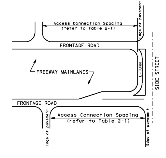
Figure 2-3. Frontage Road U-Turn Spacing Diagram
Minimum Connection Spacing Criteria for Frontage Roads (1)(2) | ||
|---|---|---|
Minimum Connection Spacing (feet) | ||
Posted Speed (mph) | One-Way Frontage Roads | Two-Way Frontage Roads |
≤ 30 | 200 | 200 |
35 | 250 | 300 |
40 | 305 | 360 |
45 | 360 | 435 |
≥ 50 | 425 | 510 |
(1) Distances are for passenger cars on level grade. These distances may be adjusted for downgrades and/or significant truck traffic. Where present or projected traffic operations indicate specific needs, consideration may be given to intersection sight distance and operational gap acceptance measurement adjustments. (2) When these values are not attainable, refer to the variance process as described in Chapter 2, Section 5. | ||