Section 2: Bridge Railing Upgrade Requirements
Section 2: Bridge Railing Upgrade Requirements
FHWA Policy
FHWA Policy
The Federal Highway Administration (FHWA) in its November 20, 2009, implementation plan for MASH, requires that bridge railing on the National Highway System (NHS) meet requirements of MASH or NCHRP Report 350:
- “Highway safety hardware installed on new construction and reconstruction projects shall be those accepted under NCHRP Report 350 or MASH.”
and
- “Agencies are encouraged to upgrade existing highway safety hardware that has not been accepted under NCHRP Report 350 or MASH:
- during reconstruction projects,
- during 3R projects, or
- when the system is damaged beyond repair.”
In the Federal Highway Administration (FHWA) January 7, 2016, MASH implementation memo, agencies are again encouraged to upgrade existing highway safety hardware, with the additional requirement that only MASH-approved devices are allowed for bridge railing installations with contracts letting after December 31, 2019.
Texas Policy
Texas Policy
TxDOT requirements for treatment of existing railing for various project classifications are outlined in the table below.
Project Classification | Railing Action | |
|---|---|---|
Preventive Maintenance (PM) and 2R | Replacement of traffic railing not complying with MASH or NCHRP Report 350 is recommended but not required as long as the minimum rail height requirement is met. Existing traffic railing complying with MASH, or NCHRP Report 350 may be raised to meet the minimum rail height requirement. Existing rail that does not meet the minimum rail height and does not comply with MASH, or NCHRP Report 350 must be upgraded to comply with MASH. | |
3R | If the structure is not widened and if no work affecting the existing railing is done as part of the 3R project. | Replacement of traffic railing not complying with MASH or NCHRP Report 350 is recommended but not required as long as the minimum rail height requirement is met. Existing traffic railing complying with MASH, NCHRP Report 350 may be raised to meet the minimum rail height requirement. |
3R | If rehabilitation work is scheduled or performed which widens the structure to either side or redecks (full-depth) any complete span of the structure, or if any work affecting the rail is done to the existing structure as part of the 3R project. | All traffic railing on the structure must comply with MASH. Railing adjacent to pedestrian walkways must comply with requirements in Chapter 3. Exceptions by approval of Design Exception or Design Waiver Request. Submit the Design Exception or Design Waiver Requests to the Bridge Division. Exceptions to compliance with MASH:
|
4R | Traffic railing must comply with MASH. Railing adjacent to pedestrian walkways must comply with requirements in Chapter 3. Exceptions by approval of Design Exception Request. | |
Hazard Elimination Program (HES) Projects | 3R or 4R criteria as applicable to the elements affected by the programmed scope of the HES project. | |
All Project Classifications | When traffic rail is upgraded to MASH, adjacent MBGF and guard fence transitions must also be upgraded. | |
NOTE
: For project classifications and work that does not require the bridge rail to be upgraded, MBGF and MBGF transitions may be upgraded without upgrading the bridge railing provided no work is done to the bridge railing other than the connection of the bridge railing to the transitions or guard fence.Existing Railing Meeting Current Standards (NCHRP Report 350)
Existing Railing Meeting Current Standards (NCHRP Report 350)
Existing railing types that are no longer used for new construction but are considered to meet the crash test criteria in NCHRP Report 350 are summarized in the following table.
Railing Type | NCHRP Report 350 Approval Level | Nominal Height | Minimum Height | Description |
|---|---|---|---|---|
T101RC | TL-3 | 27 in. | 27 in. | A version of T101 rail for retrofitting on bridges with curbs. Superseded by T131RC. |
T2 | TL-3 | 27 in. | 27 in. | Vertical faced concrete parapet with W-beam fascia; designed for vehicular traffic. Superseded by T201. |
C2 | TL-2 | 39 in. from sidewalk | 39 in. from sidewalk | Vertical faced concrete parapet with W-beam fascia and steel pipe rail; designed for vehicular and pedestrian traffic. Superseded by C201. |
T201 | TL-3 | 27 in. | 27 in. | Vertical faced concrete parapet; designed for vehicular traffic. Superseded by T221. |
C201 | TL-2 | 42 in. | 42 in. | Vertical faced concrete parapet with steel pipe rail; designed for both vehicular and pedestrian traffic. Superseded by C221. |
B201 | Not applicable* | 63 in. | 63 in. | Vertical faced concrete parapet with chain-link fence; designed for bicycle and pedestrian use. Superseded by B221. *The presence of chain-link fence makes this railing only approved for speeds of 45 mph and below. |
T202 | TL-2 | 27 in. | 27 in. | Concrete posts with concrete beam rail; designed for vehicular traffic. Superseded by T203. |
C202 | TL-2 | 42 in. | 42 in. | Concrete posts with concrete beam rail; designed for vehicular traffic. Superseded by C203. |
T203 | TL-3 | 27 in. | 27 in. | Concrete posts with concrete beam rail; designed for vehicular traffic. Superseded by T223. |
C203 | TL-2 | 42 in. | 42 in. | Concrete posts with a steel pipe rail between each post, a concrete beam rail and a steel pipe rail; designed for both vehicular and pedestrian traffic. Superseded by C223. |
B221 | Not applicable* | 68 in. | 68 in. | Vertical faced concrete parapet with chain-link fence; designed for bicycle and pedestrian traffic. *The presence of chain-link fence makes this railing only approved for speeds of 45 mph and below. |
C4 (A) | TL-2 | 42 in | 42 in | Concrete parapet with aluminum railing; designed for vehicular and pedestrian traffic. Superseded by C402. There are two heights of C4 rail-39 inches and 42 inches. The 39 inch tall version is acceptable for traffic only. |
C4 and C4 (S) | TL-3 | 42 in | 42 in | Concrete parapet with steel railing; designed for both vehicular and pedestrian traffic. Superseded by C402. There are two heights of C4 rail-39 inches and 42 inches. The 39 inch tall version is acceptable for traffic only. |
T401 | TL-3 | 33 in. | 31 in. | 18-inch concrete parapet and a steel ellipse or rectangular HSS 15 inches above the concrete. It has twin steel posts spaced a maximum of 10 ft. apart. It features a bolt anchorage system for the steel rail posts that may be drilled and epoxyanchored, allowing slip-forming of the concrete parapet. Its parapet is thicker than that of the T4(S) railing, from which its design is derived. Superseded by C402. |
T421 | TL-2 | 32 in. | 30 in. | Slanted steel posts with large round tubular rails; designed for vehicular traffic. |
T5 | TL-4 | 32 in. | 29 in. | Concrete safety shaped parapet; designed for vehicular traffic. Superseded by T501. Needs a 3 foot long vertical taper at toe of rail on upstream rail end to meet NCHRP Report 350 criteria. |
T501 | TL-4 | 32 in. | 29 in. | Concrete safety shaped parapet; designed for vehicular traffic. Superseded by T551. |
C501 | TL-2 | 42 in. | 42 in. | Concrete safety shaped parapet with steel pipe railing; designed for both vehicular and pedestrian traffic. |
T502 | TL-4 | 32 in. | 29 in. | Concrete safety shaped parapet with multiple drain slots; designed for vehicular traffic. Superseded by T552. |
C502 | TL-2 | 42 in. | 42 in. | Concrete safety shaped parapet with multiple drain slots and with steel pipe railing; designed for both vehicular and pedestrian traffic. |
T503 | TL-4 | 32 in. | 29 in. | Precast concrete safety-shaped parapet bolted to slab; designed for vehicular traffic. |
T504 | TL-4 | 32 in. | 29 in. | Precast concrete safety-shaped parapet bolted to slab and designed for box-beam and slab-beam structures; designed for vehicular traffic. |
T77 | TL-3 | 33 in. | 31 in. | Concrete curb with steel posts and two steel tube rails, designed for vehicular traffic. |
HT | TL-5 | 50 in. | 47 in. | Modified concrete safety-shaped parapet with steel railing; designed for heavy truck traffic. Superseded by T80HT. |
TT | TL-6 | 90 in. | 90 in. | Modified concrete safety-shaped parapet with concrete posts and concrete railing; designed for heavy tank truck traffic. Never issued as a standard rail type. Superseded by T80TT. |
T501SW | TL-4 | Not applicabl e | Not applicabl e | 8-foot reinforced concrete safety-shaped parapet and vertical wall; designed for use on bridges and on pavement. Never issued as a standard rail type. May also be referred to as T501NB and in heights other than 8-feet. |
TW3 | TL-3 | 29 in. | 27 in. | Concrete curb with steel posts and two steel tube rails, designed for vehicular traffic. Never issued as a standard rail type. Superseded by T1W. |
CW2 | TL-2 | 42 in. | 42 in. | Concrete curb with steel posts and four steel tube rails, designed for vehicular and pedestrian traffic. Never issued as s standard rail type. Superseded by C1W. |
T412 | TL-4 | 42 in. | 42 in. | Concrete with 6-inch windows; designed for vehicular traffic. Never issued as a standard rail type. Superseded by C412. |
T414 | TL-4 | 42 in. | 42 in. | Concrete with 6-inch windows; designed for vehicular traffic. Never issued as a standard rail type. Superseded by C412. |
LowProfile | TL-2 | 20 in. | 20 in. | Concrete rail, designed for vehicular traffic. Never issued as a standard rail type. This rail cannot be transitioned with an MBGF, so requires special details for the transition. |
PR1 | Not applicable | 42 in. | 42 in. | Steel posts with steel rails, designed for pedestrian traffic. |
PR2 | Not applicable | 42 in. | 42 in. | Concrete parapet with steel posts and steel rails, designed for pedestrian traffic. |
Minimum Bridge Railing Height
Minimum Bridge Railing Height
Minimum heights for most bridge railing types are documented in Appendix A, "Current Standard Bridge Railings in Texas" and Table 4-2. If the railing is not shown in this Manual, the minimum allowable height is as follows:
- Traffic Railing
- Low speed (less than 45 mph) – 27 inches
- High speed, TL-3 - 29 inches
- High speed, TL-4 - 36 inches
- High speed, TL-5 - 42 inches
- Combination and pedestrian railing – 42 inches.
Measuring Bridge Railing Height
Measuring Bridge Railing Height
If the bridge has no overlay, measure height as shown in Figure 4-1.
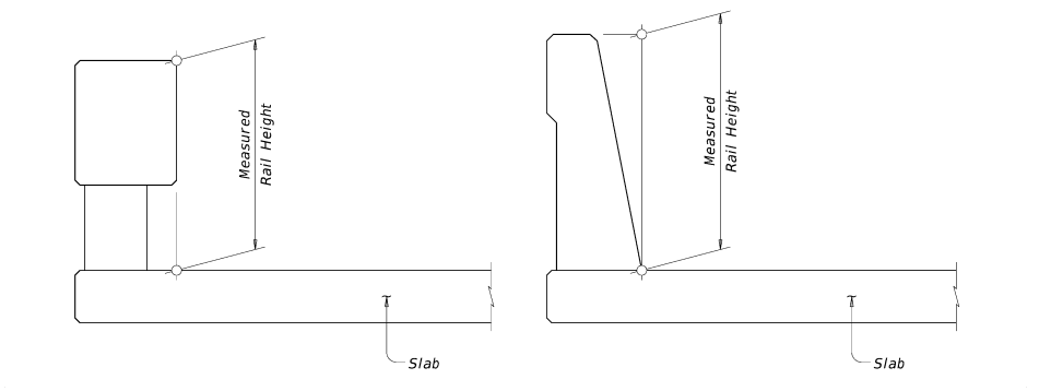
Figure 4–1: Measuring bridge railing height with no overlay
If the bridge is topped with overlay or seal coat, take two measurements if possible: 1.) On the front side of rail from the top of overlay as shown in Figure 4-2 and 2.) On the back side of rail from the concrete deck surface.
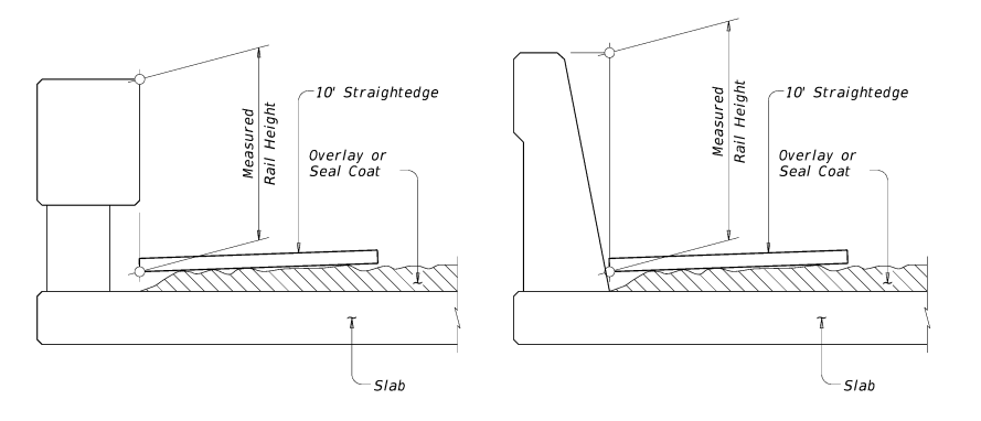
Figure 4–2. Measuring bridge railing height with overlay or seal coat
Bridge Railing Height in Pavement Overlay Projects
Bridge Railing Height in Pavement Overlay Projects
Minimum railing heights must be maintained, even during subsequent bridge maintenance overlays. In order to achieve minimum railing height, the following actions are available: Mill the existing overlay prior to new overlay application; taper the new overlay at a maximum 1 to 10 slope over the width of the shoulder to zero depth at the rail; or both.
If minimum railing height cannot be achieved with milling or tapering the overlay, the railing must be retrofitted to its minimum height when allowed by the criteria in Table 4-1. The Bridge Division is available to assist when details for raising railing heights are required.
Transition Upgrades
Transition Upgrades
When roadway guard fence is upgraded, but existing bridge railing will remain in place, customized bridge-railto-guard-fence transitions may be required. The Bridge Division is available to advise Districts on options.
Recommendations
Recommendations
Consider the following aspects of the project in the selection of a retrofit railing:
Elements of the bridge structure
- Review details of the slab and curb reinforcement of the existing bridge to determine if the slab edge is capable of being retrofitted with an adequate new railing. Note in particular:
- Slab thickness and overhang length;
- Curb width and height and reinforcement; and
- Bridge abutment wingwall conditions.
- Evaluate the effect of a full-strength retrofit on the shoulder width of the bridge. Ensure that a reduction in effective shoulder width or in sight distances at adjacent intersections will not affect safety. Also consider the following:
- Bridge width, alignment, and grade;
- Type, aesthetics, and strength of existing railing; and
- Bridge length and its potential for posting speed limits.
Characteristics of the bridge location
- Evaluate details of the location, such as the following:
- Bridge structure’s height above lower terrain or waterway;
- Approach roadway’s width, alignment, and grade;
- Position of adjacent streets and their average daily traffic;
- Posted speed at bridge, average daily traffic, and percentage of truck traffic; and
- Accident history on the bridge.
Features of the retrofit designs
- Carefully review details of potential retrofit designs, such as the following:
- Placement or spacing of new anchor bolts or dowels;
- Reinforcement anchorage;
- Approach guard fence post positioning; and
- Shoulder width required by the new railing.