Chapter 6: Load Ratings and Load Postings
Section 1: Load Ratings
Definition of Load Ratings
The Load Rating is a measure of bridge live load capacity and has two commonly used categories:
- Inventory Rating, as defined by the current AASHTOManual for Bridge Evaluation,1 is that load, including loads in multiple lanes, that can safely utilize the bridge for an indefinite period of time.
- Operating Rating, defined by the same manual, is the maximum permissible live load that can be placed on the bridge. This load rating also includes the same load in multiple lanes. Allowing unlimited usage at the Operating Rating level will reduce the life of the bridge.
Determination of Load Ratings
Currently, all Inventory and Operating Ratings are expressed in terms of an equivalent HS-truck. Prior to about 1995, many ratings were for an equivalent H-truck. The H-truck directly corresponds to single-unit trucks, which used to be common on rural highways. Today, even rural Farm- or Ranch-to-Market highways and many off-system highways are exposed to much larger vehicles; therefore, the HS-truck is more realistic. Furthermore, AASHTO Legal Vehicles (TYPE 3 Trucks), Specialized Hauling Vehicles (SHV) and Emergency Vehicles (EV) are considered in addition to the HS-truck when load rating bridges.
All bridges carrying vehicular traffic shall have load ratings, which can be assigned, assumed, or calculated load ratings.
Inventory Rating and Design Load Considerations
The Inventory Rating Item 66 (SNBI: B.LR.05) can be initially estimated to be at least equal to the design loading if no damage or deterioration exists and the original design was made using an HS load pattern for Load Factor Design (LFD) or HL-93 load pattern for Load and Resistance Factor Design (LRFD). Many old plans have a design loading shown as H-20 S16, which some raters have misinterpreted as meaning H-20. AASHTO replaced the H-20 S16 designation in 1965 with the HS-20 designation. Re-rating these bridges using LF procedures will usually increase the Inventory Rating above HS-20. Rating bridges designed between 1946 and about 1958 by current LF procedures may result in significantly different values than the original design loading. Although the plans may say designed to H-20 S-16 and Texas Highway Department (THD) Supplement No. 1, the bridge may rate significantly less than HS-20 loading. This difference is due to the more liberal effects of THD Design Supplement No. 1 described below.
In 1946, the THD issued what is commonly called THD Supplement No. 1.2 Texas was influential in the development of the AASHTO Bridge Design Specifications. However, not all the Texas opinions were immediately accepted by the AASHTO Bridge Committee, which includes all states. As a result, TxDOT used the supplement for a number of years to amend portions of the 1944 and 1949
AASHTO
Standard Specifications for Highway Bridges
34 for use in Texas. The first version of Supplement No. 1 was dated June 1946.5 The second version of Supplement No. 1 was dated September 19536 and included only those items of the 1946 version that had not been incorporated into the 1949 AASHTO Standard Specifications for Highway Bridges
.7 The primary subjects of the supplement that affected bridge design loading can be summarized as follows:- Design Overload. The 1944 AASHTO Bridge Specifications8 required an overload to be considered for all bridges designed for less than an H-20 (40,000 lbs.) or H-20 S-16 (72,000 lbs.) loading, now called HS-20 loading. The overload was to be the design truck (usually H-15) increased by 100 percent, but without concurrent loading of adjacent lanes, thus allowing single-lane load distribution. The allowable stress was to also be increased to 150 percent of the basic allowable. Texas modified this provision specifically to apply the same overload to truss counter members for all design loadings. Truss counters are those members that, for some positions of live load, will change from tension to compression. If a truss was designed H-15, H-20, or H-20 S-16, the overload was applied in determining the size of counter member.
- Lane Load Negative Moments. The 1944 AASHTO Bridge Specifications9 required for H-10, H-15, or H-20 lane loads an additional concentrated load in one other span in a continuous unit positioned to produce maximum positive and negative moments. Texas limited the distance between the concentrated loads for the lane load to a maximum of 30 ft. The H-20 S-16 truck loadings have a second axle spaced from 14 to 30 ft from the first heavy axle. The 1949 AASHTO bridge specifications10 made the lane loading negative moment requirement the same for HS-trucks. However, the 1953 THD Supplement No. 111 continued modifying the provision for continuous spans subjected to lane load by limiting the spacing between the additional concentrated load to 30 ft. This limit had the effect of reducing the lane load negative moment maximums for some continuous spans. Current specifications do not limit the distance between the two loads for negative moment lane loadings.
- Impact Load Provision. The 1944 AASHTO Bridge Specifications12 required that the shortest length of adjacent spans in a continuous unit be used for the negative moment impact value. In 1949, AASHTO changed this to the current provision of using the average length of the adjacent spans. Both versions of THD Supplement No. 11314 changed the impact provision for continuous units or other structures where discontinuous lane loadings are applied to be the loaded length as indicated by the influence line for the section of member considered.This change had the effect of slightly increasing the impact value.
- Special Axle Loads. The 1946 THD Supplement No. 115 added a provision that no axle load in excess of 24,000 lbs. should be considered in the design of floor slabs. It further required that either a single 24,000-lb axle or two 16,000-lb axles spaced four ft apart must be used for the design of H-20 and H-20 S-16 bridge floors (slabs, grids, timber) instead of the 32,000 lb axle. The provision was dropped in the 1953 THD Supplement No. 116 because the 1949 AASHTO Bridge Specifications17 included the provision specifically for concrete bridge slabs. The AASHTO Bridge Specifications further limited the 24,000-lb axle to slab spans under 18 ft and the two 16,000 lb axles for slab spans over 18 ft.This provision had the effect of reducing the design load for many slab spans designed during that time. It has been found that some beams have been designed in Texas using the single 24,000-lb axle. It is believed to be an error for beams to have been designed this way. For this reason, carefully evaluate any plans prepared during the period between approximately 1949 and 1961 with a design load of H20 or H20 S-16 that also had the THD Supplement No. 118 notation.
There are three acceptable approaches to determining inventory and operating ratings: assigned, assumed, and calculated.
Assigned Load Ratings
Per the September 29, 2011 FHWA Assigned Load Rating Memo, FHWA has determined that the Inventory and Operating level ratings may be assigned based on the design load when:
- The bridge was designed using either the AASHTO Load and Resistance Factor Design (LRFD) or Load Factor Design (LFD) methods to at least HL-93 or HS-20 live loads, respectively. The engineer shall provide or verify that the proper design plans showing the required design load and design method are available in the Bridge Inspection Management System, AssetWise; and
- The bridge was built in accordance with the design plans; and
- No changes to the loading conditions or the structure condition have occurred that could reduce the inventory rating below the design load level; and
- An evaluation has been completed and documented, determining that the force effects from State legal loads or permit loads do not exceed those from the design load; and
- The checked design calculations, and relevant computer input and output information, must be accessible and referenced or included in the individual bridge records
TxDOT’s Load Rating Statement (form 2495) for assigned ratings is applicable when the following conditions are met:
- The bridge must be designed using AASHTO Load and Resistance Factor Design (LRFD) or Load Factor Design (LFD) methods to at least HL-93 or HS-20 live loads, respectively.
- The principal structural elements of Items 58 (SNBI: B.C.01), 59 (SNBI: B.C.02), 60 (SNBI: B.C.03), and 62 (SNBI: B.C.04) must have a condition rating greater than or equal to 5.
- The bridge elements in their current state continue to maintain structural capacity equal to the original design.
For assigned load ratings, the coding for items 63 (SNBI: B.LR.04) and 65.1 (SNBI: B.LR.04) must be "C - Assigned rating based on LRFD reported in tons" (SNBI: AR) or "A - Assigned rating based on LFD reported in tons" (SNBI: AR) respectively.
Prestressed beams designed with AASHTO Standard Specifications 1961 or later included strengths checks and are considered to meet the requirements for Load Factor Design.
Assumed Load Ratings
Assumed load ratings can be utilized for concrete or masonry structures that do not have plans or plans do not contain adequate structural information to perform calculated load ratings. These types of ratings are based on field conditions of the structure and documented engineering judgement. The following conditions must apply for an assumed load rating to be applicable:
- The bridge has been carrying unrestricted traffic for at least 4 years; and
- The bridge shows no signs of significant distress; and
- The simple span bridge's span-to-depth ratio of the main members does not exceed approximately 20; and
- Construction details such as slab thickness and reinforcement cover over any exposed reinforcing conform to specifications at the time of the estimated construction; and
- Appearance of the bridge indicates that construction was performed by a competent builder.
Additional consideration for rating concrete bridges with unknown reinforcing:
- Concrete decks that are a minimum of 6 inches thick and have an Item 58 (SNBI: B.C.01) condition rating greater than or equal to 5 shall not control the overall load rating of a bridge. If Item 58 (SNBI: B.C.01) <5, assume IR=HS15 [27 Tons (SNBI: RF=0.75)] and OR=HS20 [36 Tons (SNBI: RF=1.00)], or lower and post at Inventory level if the rating of the deck is controlling.
If condition ratings meet the criteria in Figure 6-1
Error! Reference source not found
., then assume an Inventory Rating of HS15 [27 Tons (SNBI: RF=0.75)] and an Operating Rating of HS20 [36 Tons (SNBI: RF=1.00)]. If the condition rating criteria is not met, assume IR = HS15 [27 Tons (SNBI: RF=0.75)] and OR = HS20 [36 Tons (SNBI: RF=1.00)] or lower based on engineering judgement, and post the bridge at the Inventory level. The same ratio of SHV and EV rating factors shall be assumed. For example, if inventory rating is assumed to be HS15 and operating rating is assumed to be HS20, AASHTO Legal Vehicles, SHV and EV operating rating factors shall be 1.00.A comparative original design rating can be used to estimate the amount of reinforcing in the main members. Normally, if the design was done prior to about 1950 and the above five considerations are met, then the amount of reinforcing can be estimated based on a percentage of the gross concrete area of the main beams (if tee-beam construction), or depth of slab (if slab construction).
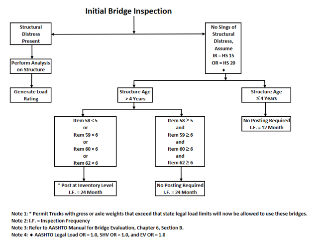
Figure 6-1. Load Ratings for Concrete Bridges without Plans
Calculated Load Ratings
A bridge shall have calculated load rating if it is not eligible for Assigned or Assumed Load Rating. Traditionally Inventory or Operating Ratings were determined using either Load Factor Rating (LFR), Load and Resistance Factor Rating (LRFR), or Allowable Stress Rating (ASR) methods. The selection of calculated load rating method shall be in compliance with the FHWA memo of “Bridge Load Ratings for the National Bridge Inventory” dated on 10/30/2006.
LFR or LRFR may be used for most bridges. ASR should be used only for timber and masonry bridges.
A Load Rating Summary Sheet should be completed for all calculated load ratings.
Customary Rating Procedures
When a bridge was originally designed, the designer often had to select the next size of reinforcing bar, size of steel beam, or thickness of cover plate to meet the design stress criteria. Sizes that were larger than the theoretically perfect size of member result in Inventory Ratings significantly higher than the design loading. However, the design loading and date of original construction are important parts of the bridge data since they often provide a basis for determining initial routing of overload permits.
If the original design load was an H-load, such as H-15 or H-20, then the equivalent HS Inventory Rating will usually be significantly less, numerically. For example, an H-15 design might rate at HS-12. However, this difference means that the total inventory HS-load capacity is 43,200 lbs. (two 19,200 pounds tandem axles and one 4,800 lbs. single axle, totaling 21.6 tons) as compared to the H-15 design of 30,000 pounds (15 tons).
Determine the original design load from a review of the bridge plans if available. If the structure substantially matches an old TxDOT standard bridge, and is from an appropriate time period, then the design load for that standard can be used for Design Load, Item 31 (SNBI: B.LR.01). (Note: this would be difficult to do with Pan Girders.) Enter an appropriate notation about this in the Bridge File. Use caution accepting the design load when the Design Load references a modification by THD Design Supplement No. 11920 due to circumstances described above.
Do not consider temporary repairs for Inventory or Operating Ratings. However, take temporary repairs into account when assigning the operational status code of Item 41 (SNBI: B.PS.01) to the structure. Temporary repairs are to be considered for the operational status code only until a more permanent repair is made. Do not use temporary repairs for more than four years.
Use all field information and conventional analysis techniques when the design loading is unknown or deterioration exists. Even when the design loading is known, the only acceptable method for accurate load rating is to perform calculations based on the plans and known field measurements.
Mill Test Study and Utilization of Results
When mill certifications are not available, material properties for a load rating will be based on recommendations for minimum material properties in the MBE. However, experience has shown that the default material strength values, especially for steel reinforcement and structural steel, are quite conservative when compared to results from mill certificates. (TxDOT maintains a large inventory of these historic mill test certificates.)
This observation initiated an effort to establish a minimum probable estimate of yield strength based on steel grade so that TxDOT could use a more representative minimum yield strength for load ratings when mill test reports are not available. TxDOT implemented a study to scan and analyze microfilm containing the mill certifications from 394 unique CSJs and establish a recommended yield strength based on statistical analysis. For reinforcing steel, a total of 3,976 yield strength data points for Grade 40, 90 data points for Grade 33, 1,587 data points for Grade 50, and 74 data points for Grade 60 were analyzed. For structural steel, a total of 548 data points for A373, 713 data point for A7, and 2,030 data points for A36 were also analyzed. The results are summarized in Tables 6-1 and 6-2 below.
Grade 33 | Grade 40 | Grade 50 | Grade 60 | |
|---|---|---|---|---|
Specified minimum yield strength (ksi) | 33.0 | 40.0 | 50.0 | 60.0 |
Recommended yield strength (ksi) | 36.0 | 43.0 | 50.0 | 61.0 |
A373 | A7 | A36 | |
|---|---|---|---|
Specified minimum yield strength (ksi) | 32.0 | 33.0 | 36.0 |
Recommended yield strength (ksi) | 37.5 | 36.4 | 38.0 |
The increased steel yield strength can be applied to load factor ratings on bridges which were designed using Allowable Stress or Load Factor methods. The increase in steel grades are not to be applied for bridges designed with the AASHTO LRFD method. The AASHTO MBE 3rd Edition states that the resistance factors for LRFD have been calibrated with the
consideration of a higher yield strength than that of the stated minimum grade. Therefore, the structural capacity calculated by AASHTO LRFD methods already includes the effect of higher yield strengths. The application of these higher yield strengths is limited to bridge elements in fair or better condition without significant distress which would otherwise cause the bridge to be posted for legal loads.
Ratings for Unusual Bridges
Unusual bridges, such as those composed of old railroad flat cars, can be rated, but ensure that the critical rating component is considered. For instance, flat cars were originally designed for a maximum point load combined with a uniform load over the whole car. When used for traffic loadings, even though the main two-girder members may give a good equivalent HS load rating, the transverse stiffening members and floor beams often control the live load capacity.
Another unusual type of bridge in Texas is the continuous cast-in-place (CIP) flat slab. Most of these bridges were designed in the 1940s and 1950s with an H-15 or H-20 load pattern. Unfortunately, the design negative moments were from the single truck load in one span. As a result, these bridges may be under-designed for HS-loadings and, may require a load restriction. Procedures for an HS-20 design load use a lane load with two concentrated loads in adjacent spans for the controlling negative moment case for longer continuous bridges. For shorter, continuous bridges, an HS-20 design uses two heavy axles of the HS-20 load pattern at variable spacing in adjacent spans. However, the current AASHTO Bridge Specifications do not differentiate between single-and multiple-lane distribution factors for slab bridges. As a result, this type of bridge has greater strength for multiple trucks positioned in the middle of the bridge span. Some structural evaluators make live load distribution adjustments based on the number of lanes loaded for flat slab bridges. Exercise care and properly correlate it to two- or three-dimensional methods of analysis to use this procedure.
Concrete Box Culvert Load Rating by Design Load Correlation
TxDOT carried out a project to determine the load rating of concrete box culverts reflective of in-service performance. The project included load testing and finite element analysis on a sample of culverts to correlate design loads to load ratings. Per the report, the following load ratings were determined for qualifying concrete box culverts. The report is available on the Bridge Division website.
Load Ratings* | |||||||||||
HS-20 | SU4 | SU5 | SU6 | SU7 | EV2 | EV3 | |||||
INV | OPR | INV | OPR | INV | OPR | INV | OPR | INV | OPR | OPR | OPR |
14.8 | 24.8 | 0.95 | 1.58 | 0.84 | 1.41 | 0.78 | 1.30 | 0.76 | 1.27 | 1.28 | 1.03 |
*HS-20 ratings are reported in HS format. All other ratings are reported as rating factors.
The above ratings are applicable to concrete box culverts that meet the following three criteria:
- Condition rating Item 62 (SNBI: B.C.04) must be greater than or equal to “5”. This requirement will ensure that this approach is only applied to structures in fair or better condition.
- Year built Item 27 (SNBI: B.W.01) is not later than 1999. This requirement is to capture culverts designed by Allowable Stress Design (ASD) method.
- Item 41 (SNBI: B.PS.01) is coded as “A” - open to unrestricted traffic (SNBI: Open (O)).
If Table 6.3 is utilized to determine load ratings of a culvert, the culvert does not need to be load posted, and Figure 6.4 or Figure 6.5 (On/Off System Load Posting Flowchart) is not applicable.
Concrete box culverts that do not meet the above three requirements, nor requirements for Assigned Load Rating must have either calculated load rating or assumed load rating. Use the guidelines in the section “Assumed Load Ratings” for concrete culverts without plans.
If a concrete box culvert bridge has another type of structure such as an expansion slab, the non-culvert part shall be evaluated by one of the three load rating methods: Assigned, Assumed, or Calculated ratings. Report the lower load rating of either the culvert or the nonculvert parts for the structure.
Items 63 and 65.1 (SNBI: B.LR.04), methods used to determine Operating and Inventory Ratings, will be coded as “1” – Calculated Load Rating Based on Load Factor (LF) (SNBI: LFR).
The following flow chart shows the culvert load rating procedure.
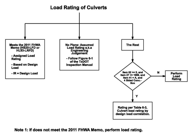
Figure 6-2. Load Ratings for Concrete Box Culvert
H- and HS-Load Ratings
Previously, all ratings were done with the equivalent H-truck and HS-truck. Currently, all ratings are only done with the HS-truck. A moment equivalency conversion from H- to HS-ratings is not recommended since this process would assume that the structure was exactly designed for the given H-loading. In addition, continuous spans cannot be converted by this process. Most structures have a degree of capacity past the design H-load, particularly since load distribution assumptions of the AASHTO Bridge Specifications21 have been made more liberal since the time many structures were commonly designed using H-loads. However, some bridges were intentionally designed with AS methods to a 5 percent overstress for some components.
It is not acceptable to ratio the design live load moments for an H-truck to the same moment for an equivalent HS-truck. For instance, if a 48-ft simple-span bridge has a design load of H-15, the design load for moment equivalency would be HS-10.8. However, due to the above reasons, the actual rating based on LF methods might easily be HS-9 or HS-13. A LF rating must be generated due to the uncertainty of the actual design practice used.
AASHTO Legal Vehicle (Type 3, Type 3S2, and Type 3-3) Load Ratings
When calculated load ratings are required, provide operating rating factors for HS loading, AASHTO legal vehicles, Type 3, 3S2 and 3-3.
Specialized Hauling Vehicle (SHV) Load Ratings
On November 15, 2013, FHWA delivered a memo to require that all bridges be load rated for Specialized Hauling Vehicles (SHVs) as defined in the current AASHTO
Manual for Bridge Evaluation (MBE)
and load restricted if necessary. These single unit trucks have multiple axles that are closely spaced and moveable axles that raise or lower if needed, resulting in higher concentrated loads within the shorter axle spacing. The MBE defines 4 SHV trucks: SU4, SU5, SU6, SU7 and one Notional Rating Load (NRL). The Notional Rating Load, NRL, may be used as a screening load model for single-unit trucks that meet Formula B. Bridges that result in RF ≥ 1.00 for the NRL loading will have adequate load capacity for all legal single-unit Formula B truck configurations up to 80,000 lbs. Figure 6-3 shows the detailed load configurations for these load rating trucks. When SHV load ratings are performed, present them to the State in Operating Rating factors. TxDOT has compiled a guide to the load rating of structures for SHVs, available on the Bridge Division webpage.Emergency Vehicle (EV) Load Ratings
On November 3, 2016, FHWA delivered a memo to require load rating bridges that are on the Interstate System and within reasonable access to the Interstate System for Emergency Vehicles (EVs) as defined in Fixing America's Surface Transportation Act (FAST Act) (Pub. L.114-94). Since Texas allows EVs to operate legally on all bridges, all bridges in Texas must be evaluated for EVs. By definition, an emergency vehicle is used to transport personnel and equipment to respond to emergency situations such as fires and other hazardous conditions. The gross vehicle weight limit for emergency vehicles is 86,000 pounds. Two emergency vehicles were defined by FHWA, EV2 and EV3. Figure 6-3 shows the detailed load configurations for the 2 EV load rating models. Only bridges with inventory rating less than HS20 shall be load rated for EVs. When EV load ratings are performed, present them to the State in Operating Ratings factors. TxDOT has compiled a guide to the load rating of structures for EVs, available on the Bridge Division webpage.
-Load-Ratings/H_HS_AASHTO_Type_3_Trucks_SHV_and_EV_Truck_Load_Configurations.png/_jcr_content/renditions/original)
Figure 6-3. H, HS, AASHTO Type 3 Trucks, SHV and EV Truck Load Configurations
Substructure Load Ratings
Refer to AASHTO Manual for Bridge Evaluation for procedures regarding load rating of substructures. Substructures do not need to be routinely load rated unless the engineer believes they have the potential to control the load rating for the bridge or presence of structural deterioration triggers a load rating to verify live load carrying capacity of the bridge. Only load carrying member(s) of the substructure with a poor condition rating (NBI 4 or less) would trigger the need of a new load rating.
A substructure load rating is required if the engineer believes that a bridge was not built based on solid engineering design.