Design Criteria for Specific Wall Types

Spread Footing Walls
. The engineer specifying this type of wall for inclusion in the plans is responsible for overall (global) stability of the wall. Ensure that the actual wall geometry and loading conditions apply to the standard drawing selected. Ensure that interruptions to the stem or footing steel by utilities or curved sections of walls do not compromise the design and performance of the wall. Ensure that skewed abutment ends do not pose conflicts with the footprint of the wall. Provide guidance or structural details when deviations from the wall standard drawings are warranted. Standard drawings provide a choice between slope and no slope above wall or surcharge load footings: selection of the appropriate standard drawing is a function of the loading, geometry, and site condition Standard drawings are developed based on the design parameters for foundation and retained soils of a cohesion of zero, a friction angle of 30 degrees for the retained and foundation soil, and a unit weight of 120 pounds per cubic foot for both. Give special consideration to walls subject to inundation. Considerations include drainage and draw-down stability analysis. Standard specification Item 423 governs the design and construction of this wall type.
Provide expansion joints at intervals not exceeding 96 feet and contraction joints at intervals not exceeding 32 feet.
MSE Walls
. The engineer specifying this type of wall for inclusion in the plans is responsible for overall (global) stability and for providing information to complete the RW (MSE) DD sheet. MSE wall should be avoided in zones of potential scour or erosion. MSE wall suppliers are responsible for internal stability of the walls and for ensuring that external stability, as defined on the RW (MSE) standard, is met. The friction angle of both the foundation soil and the retained soil must be defined by the wall designer and input on the TxDOT RW(MSE) DD sheet. Default minimum earth reinforcement is set at 8 ft. or 70 percent of the wall height, whichever is greater. The wall designer is responsible for ensuring that the minimum earth reinforcement length selected on the RW(MSE)DD sheet satisfies the resistance factor requirement with the defined friction angle of the foundation soil and the retained soil. To ensure proper performance of the wall in place, evaluate project-specific requirements for wall backfill type, wall embedment, wall drainage, conflicts within the wall reinforced zone, and other considerations as necessary. Give special consideration to walls that are subject to inundation. Type BS backfill is the default backfill for permanent walls. Type DS backfill must be specified for walls that are subject to inundation. Analyze walls subject to inundation for 3 ft. of draw-down. Refer to the RW(MSE)DD standard for guidance on the draw down design condition. Walls to be placed in front of bridge abutments should have a 2 -ft. minimum and 3-ft. desirable clearance from back of wall panel to face of abutment cap to facilitate wall construction. Standard specification Item 423 governs the design and construction of this wall type.
Evaluate MSE walls for total and differential settlement for all applicable dead and live load combinations at Service I limit states in accordance with AASHTO LRFD Bridge Design Specifications. Total settlement should be less than 4 inches unless approved by the TxDOT State Geotechnical Engineer. Limit differential settlement as defined in the AASHTO LRFD Bridge Design Specifications, C11.10.4.1-1. Slip joints may be required to limit effects of differential settlement.
Temporary MSE or Welded Wire Face Wall
. Temporary Walls have a service life no longer than 3 years. The engineer who selects this type of wall for inclusion in the plans is responsible for the overall (global) stability of the wall and for providing information to complete the RW (TEW) DD sheet. Temporary MSE wall suppliers are responsible for internal stability of the walls and for ensuring that external stability, as defined on the RW (TEW) standard, is met.
If the site condition soil properties differ from those indicated above, then the RW(TEW) standard will need to be modified to reflect the actual site soil properties.
Set the minimum earth reinforcement length to 6 ft. To ensure proper performance of the wall in place, evaluate project-specific requirements for wall backfill type, wall embedment, wall drainage, conflicts within the wall reinforced zone, and other considerations as necessary. Give special consideration to walls that are subject to inundation. Type C backfill is the default backfill for temporary walls. Specify Type D backfill for walls that are subject to inundation. Analyze walls subject to inundation for 3 ft. of draw-down. Backfill the 2-ft. zone immediately behind the facing with clean coarse rock or cement-stabilized backfill. A designer who prefers to use coarse rock or cement-stabilized backfill must state this in the plan documents.
If a temporary MSE wall will be in service for longer than 3 years, the designer must state this in the plan documents to ensure that the wall supplier provides a design with an adequate service life. Temporary MSE walls placed adjacent to permanent MSE walls must be detailed with earth reinforcement that will prevent corrosion of the permanent earth reinforcements due to contact of dissimilar metals. This may be accomplished by providing galvanized or synthetic earth reinforcements for the temporary MSE walls.
Standard specification Items 403 and 423 govern construction of this wall type.
Concrete Block Walls
. The engineer who selects this type of wall for inclusion in the plans is responsible for overall (global) stability of the wall and providing information to complete the RW(CB)DD sheet. Concrete block wall suppliers are responsible for internal stability of the walls and for ensuring that external stability, as defined on the RW (CB) standard, is met.
If the site condition soil properties differ from those indicated above then the RW(CB) standard needs to be modified to reflect the actual site soil properties.
Concrete block walls may be classified as either structural or landscape walls. The minimum strap length varies depending on the wall function. Minimum earth reinforcement lengths are 6-ft. for walls designated as landscape walls, and 8-ft. otherwise. To ensure proper performance of the wall in place, evaluate project-specific requirements for wall backfill type, wall embedment, wall drainage, conflicts within the wall reinforced zone, and other considerations as necessary. Type BS backfill is the default for permanent walls. Give special consideration to walls that are subject to inundation. Specify Type DS backfill and analyze these walls for 3 ft. of draw-down. The maximum particle size of the select backfill is limited to ¾" for nonmetallic reinforcements. Consult the RW(CB) and RW(CB)DD standard drawing for guidance on wall definition and design. Standard specification Item 423 governs the design and construction of this wall type.
Tied-Back Walls
. The prestressed ground anchors (tie backs) are nearly horizontal elements that are drilled, grouted, and stressed in place. Most common anchored walls are anchored sheet pile walls and soldier pile walls. Determine tied-back loads and soldier pile bending moments from the apparent earth pressure diagrams. Fill and live load surcharges are included in the pressure diagram. Determine loads and moments by the tributary area method. The minimum tie-back length is 25 ft. This length is composed of a minimum 15-ft. debonded length and a minimum 10-ft. bonded length. Minimum tie-back length as specified AASHTO LRFD Bridge Design Specifications Article 11.9 is determined by EOR in the contract plans, yet final length of the tie-back is determined by the wall contractor. Anchor loads and soil conditions may warrant tied-back anchors on the order of 60 to 70 ft. long. The anchors are then stressed to the load specified in the construction drawings. Consider the distance the tie backs will project behind the wall and any potential conflicts with subsurface obstructions or right of way limitation. Ensure that tie backs have a minimum 6-in. clear cover from any obstructions. Obtain permanent easements for tie backs that cross the right-of-way line. Consider equipment accessibility due to horizontal and vertical clearance restrictions. Standard specification Item 423 governs the construction of this wall type and is supported by the special specification Prestressed Ground Anchors.
Soil Nailed Walls
. Soil nails are nearly horizontal elements that are drilled and grouted in place. Walls are typically designed using limit state equilibrium software programs such as Goldnail, SNAP-2, Slide2, SnailPlus or SNAILZ. Design in accordance with AASHTO LRFD Bridge Design Specifications Article 11.12. Consider the distance the nails will project behind the wall and any potential conflicts with subsurface obstruction or right of way limitation.
Evaluate soil corrosion for permanent walls per AASHTO LRFD Bridge Design Specifications Article 11.12.8, use the following minimum criteria:
  • Hole diameter — 6 in.
  • Bar size — #6
  • Grade — 75 ksi for permanent walls
  • Bars — epoxy-coated or galvanized, Dywidag or Williams threadbar, or equivalent
Standard specification Item 423 Retaining Walls and Item 410 Soil Nail Anchor govern construction of this wall type.
Ensure that nails have a minimum 6-in. clearance from any obstructions. Obtain permanent easements for nails that cross the right-of-way line. The top of the wall should be no more than 2 ft. above existing grade to ensure constructability of the soil nail wall; special design considerations are required when this distance is exceeded. Nail spacing depends on project-specific site and loading conditions. A 3-ft. to 4.5-ft. vertical spacing and a 3.0-ft. to 4.5-ft. horizontal spacing is typical. Soil strengths used in the design of soil nail walls are typically determined from correlations of strength to Standard Penetration Test values conducted through the embankment to be nailed. Use nominal strengths in the analysis. Design walls considering the proposed wall geometry and loading. Limit head strength to avoid an unbalanced design. Unrealistic or high head strength results in shorter nails and causes the lowest nails to carry a disproportionate amount of load.Final verification on design should include a global (overall) check using the analysis mode of the design program used or an independent slope-stability program that is capable of modeling soil nail anchors. Consider equipment accessibility due to horizontal and vertical clearance restrictions.
Rock Nailed Walls
. Rock nail walls are used in materials classified as rock and have SPT values that meet refusal criteria. Confirm that site conditions are conducive for rock nails. Rock Nailed Wall design is based on empirical equation and should consider the dip, bedding thickness, Rock Quality Designator, percent recovery, joint spacing, and joint pattern of the rock formation. Smaller holes than those used in soil nail walls, but with a diameter not less than 4 inches, are appropriate for rock nailed walls. Adjust nail lengths to ensure that the nailed rock mas is inherently stable in the primary modes of failure (sliding and overturning). Standard specification Item 423 Retaining Walls and Item 411 Rock Nail Anchors govern construction of rock nail wall type.
Consider the distance the rock nails will project behind the wall and any potential conflicts with subsurface obstructions or right of way limitations. Ensure that nails have a minimum 6-in. clear cover from any obstructions. Obtain permanent easements for nails that cross the right-of-way line. Locate the top of wall no more than 2 ft. above existing grade to ensure constructability of the rock nail wall; special design considerations are required when this distance is exceeded. Consider equipment accessibility due to horizontal and vertical clearance restrictions.
Drilled Shaft Walls
. Drilled shafts are vertical elements that are drilled and concreted in place. They vary in size, diameter, and spacing depending on soil conditions, loading, and wall geometry. Derive wall loading using a Coulomb analysis. Soil information necessary for design includes friction angle, cohesion, and unit weight. Determine soil strengths below the proposed ground line at face of wall from correlations of strength to Standard Penetration Test values. Use nominal strengths in the analysis. The following soil strength reductions can be used in design:
  • Reduction based on close shaft spacing (per AASHTO LRFD Article 10.8.3.6), refer to reduction within the following Figure 6-1.
  • Reduction of surface soil strength based on expected swelling/softening of the soil
Sample alt text
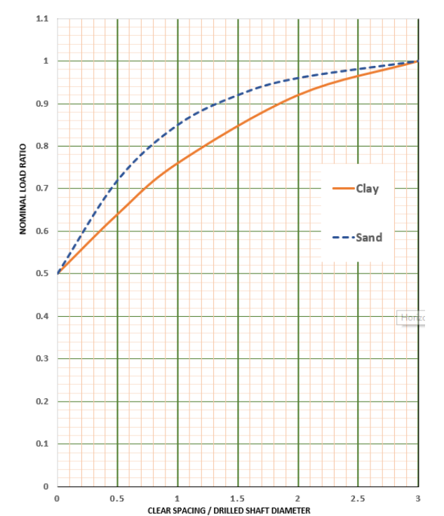
Figure 6–1. Nominal Load Ratio vs. Clear Spacing/Drilled Shaft Diameter
Design the walls iteratively, varying the length of shaft for successive runs. Make a plot of shaft embedment versus top of shaft deflection to determine when additional embedment does not result in a reduced deflection. The minimum embedment length that results in no additional top of shaft deflection is defined as the depth to fixity. An acceptable approach is to terminate the shaft at a depth 33% longer than minimum embedded depth to fixity. Maximum tolerable top of shaft deflection is set at 1% of the exposed wall height. The maximum steel reinforcement within concrete is 2.5% to 3% as limited by reinforcing spacing requirements. Minimum clear spacing between adjacent shafts is set at 1 ft. Design wall fascia to account for the maximum earth pressure at the bottom of the wall. The load applied to the fascia shall be applied through the window between the shafts assuming simple supports at the centerline of the shafts. The Contractor is responsible to ensure that face stability is maintained between shafts throughout construction. Address this by a note in the plans. Consider equipment accessibility due to horizontal and vertical clearance restrictions. Standard specification Item 416 Drilled Shafts and Item 423 Retaining Walls govern construction of this wall type and are supported by special specification Prefabricated Soil Drainage Mat.
Sheet Piles and Soldier Pile Walls
. Sheet piles and soldier piles provide lateral resistance through the flexural resistance of structural members through cantilevering and embedment into founding soil. In most conditions, these walls can accommodate an exposed height to a maximum of 15 feet. Exposed height usually depends on the acceptable limit of deflection at the top of the wall. Walls taller than this or with exceeding deflection limits require the addition of anchors in the form of a deadman or tieback. Design in accordance with AASHTO LRFD Bridge Design Specifications Article 11.8 non-gravity cantilevered walls.