Bridges
Boring Locations and Spacing
- Two test holes minimum per bridge
- Test holes must be located 100 ft or less from the anticipated center of each bent/substructure and each abutment
- Test holes must be located 50 ft or less from the anticipated center of any monoshafts used on the bridge
- Do not space test holes greater than 300 ft. apart along the bridge centerlineTest holes from adjacent bridges can be used to fulfill the above criteria, granted they are deep enough and collect sufficient sampling information and results. Feature(s) being bridged or beneath the deck are inconsequential to location and spacing criteria. Access and right of way issues occur on any project and are reason to offset borings but contact Geotechnical Branch for major deviations to the above criteria or AASHTO LRFD Article 10.4.2. The following figures display example boring location plans for common types of bridge structures.
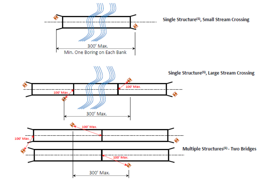
Note (1): The transverse effect of test holes as shown may not be as critical as it for Multiple Structures with wide separation (e.g., >300 ft between bridges). The holes may be placed all along one side of the structures or directly along centerline of proposed roadway. Consult with Geotechnical Branch for more guidelines.
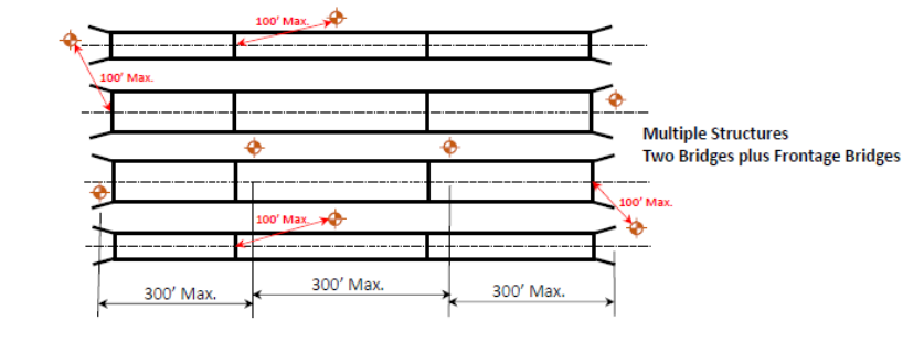
Figure 2–1. Minimum number of test holes for common types of structures
Boring Depth
anticipated loading
, or the results of previous or legacy TCP tests and correlation graphs. When SPT data is used to judge probable founding or tip elevations, consider elevations where SPT refusal occurred in the legacy borings. Consider the need for borings with depths greater than 20 ft. below the anticipated tip elevations for foundations on major structures or other cases of high or unusual loading conditions.Depending on the strength of the geomaterial estimated from the SPT blow counts and Rock Quality Designation (RQD) during the drilling operation, it may be necessary to adjust the termination depth of borings from the planned depths. Engineering decisions of early termination of borings and/or extending borings beyond the planned depths shall be made by a competent geotechnical engineer based on realtime SPT blow counts and RQD. Typically, drill deep enough until one of the following conditions are met:
- In non-water crossings and minor stream crossings, early termination of the boring depth at no shallower than 60 feet when drilling within bedrock when 25ft of continuous core within moderately weathered to nonweathered, hard to very hard rock had been recovered.
- In major stream crossings, rivers, and lake crossings, early termination of the boring depth at no shallower than 80 ft when drilling within bedrock when 40ft of continuous core within moderately weathered to nonweathered, hard to very hard rock had been recovered.
Stream Crossings
Major stream crossings require borings in the channel if no existing data is available. A site inspection by the driller or logger is necessary to evaluate site accessibility and special equipment needs.
Karst Features
Grade Separations
Bridge Field Exploration
- Boring spacing. Space borings near each abutment of the proposed structure plus enough intermediate borings to determine the depth and location of all significant soil and rock strata. If a reasonable correlation between boring and testing information (for example, SPT data, Pocket Penetrometer results, stratigraphy) cannot be made, consult with the design engineer to determine the need for additional borings.
- Soil sampling and testing. Conduct Standard Penetration tests (SPT) in accordance with AASHTO T 206 or ASTM D1586 every 5-ft. interval beginning at 5-ft depth from the surface. Where cohesive soils are observed collect thin-walled Shelby Tube samples in accordance with AASHTO T 207 or ASTM D1587 at the intermediate locations between SPT samples. Rock core drilling and sampling should be performed in accordance with AASHTO T 225.
- Near surface soil layer test. Test soft near surface soil layers (0 to 20 feet) as directed under the subsection in this chapter titled Slopes and Embankments.
- Soil and bedrock classification. Complete soil and bedrock classification and log record for each boring on the logs in accordance with Chapter 4, Soil and Bed Rock Logging.
- Ground water. Include ground water elevation measurements (including date of measurement) as part of the data acquisition. Obtain an additional groundwater elevation minimum 15 minutes after the initial encounter. Site conditions or the design objectives may require installation of piezometers to establish a long-term or steady state ground water conditions.